Reviews
Armor
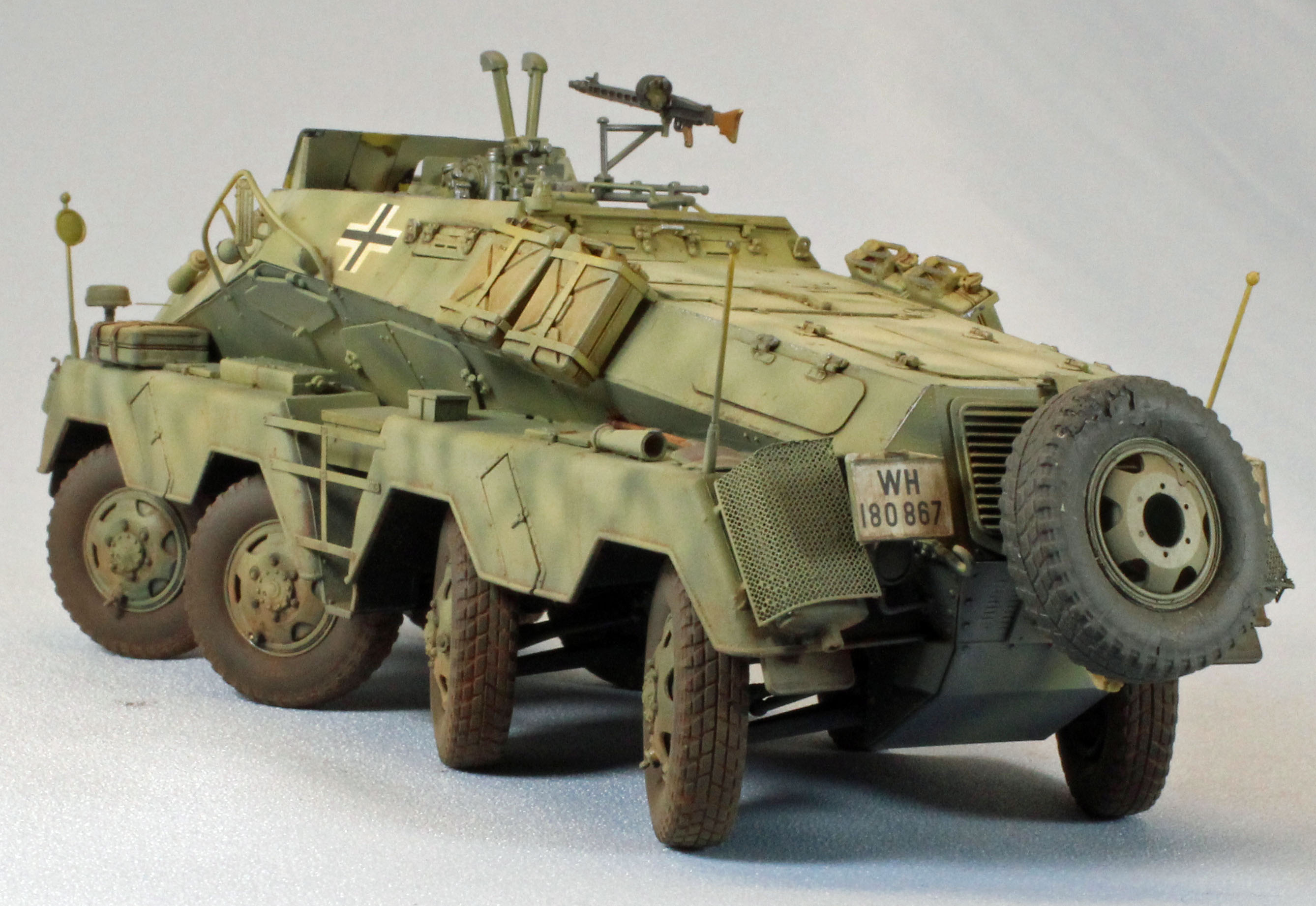
PanzerFunkwagen Sd.Kfz. 233 8 Rad 7.5cm
by Eric Christianson
 Model: PanzerFunkwagen Sd.Kfz. 233 8 Rad 7.5cm
Reviewed by: Eric Christianson, IPMS # 42218
Scale: 1/35
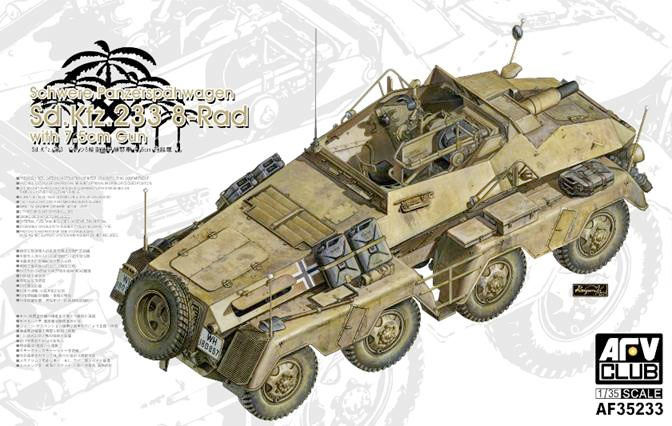
Company: AFV Club
Price: $54.00
Product/Stock #: AF35233
Website: AFV Club
Product Web Page: View
Product provided by: AFV Club
Kit Background
AFV Club has released an updated version of their original (excellent) eight-wheeled Sd.Kfz. 232 – this time representing an open-topped, -233 version armed with the 7.5 cm KwK 37 L/24 main gun. While this kit has been out for some time, the specific vehicle type has remained under-represented in the industry.
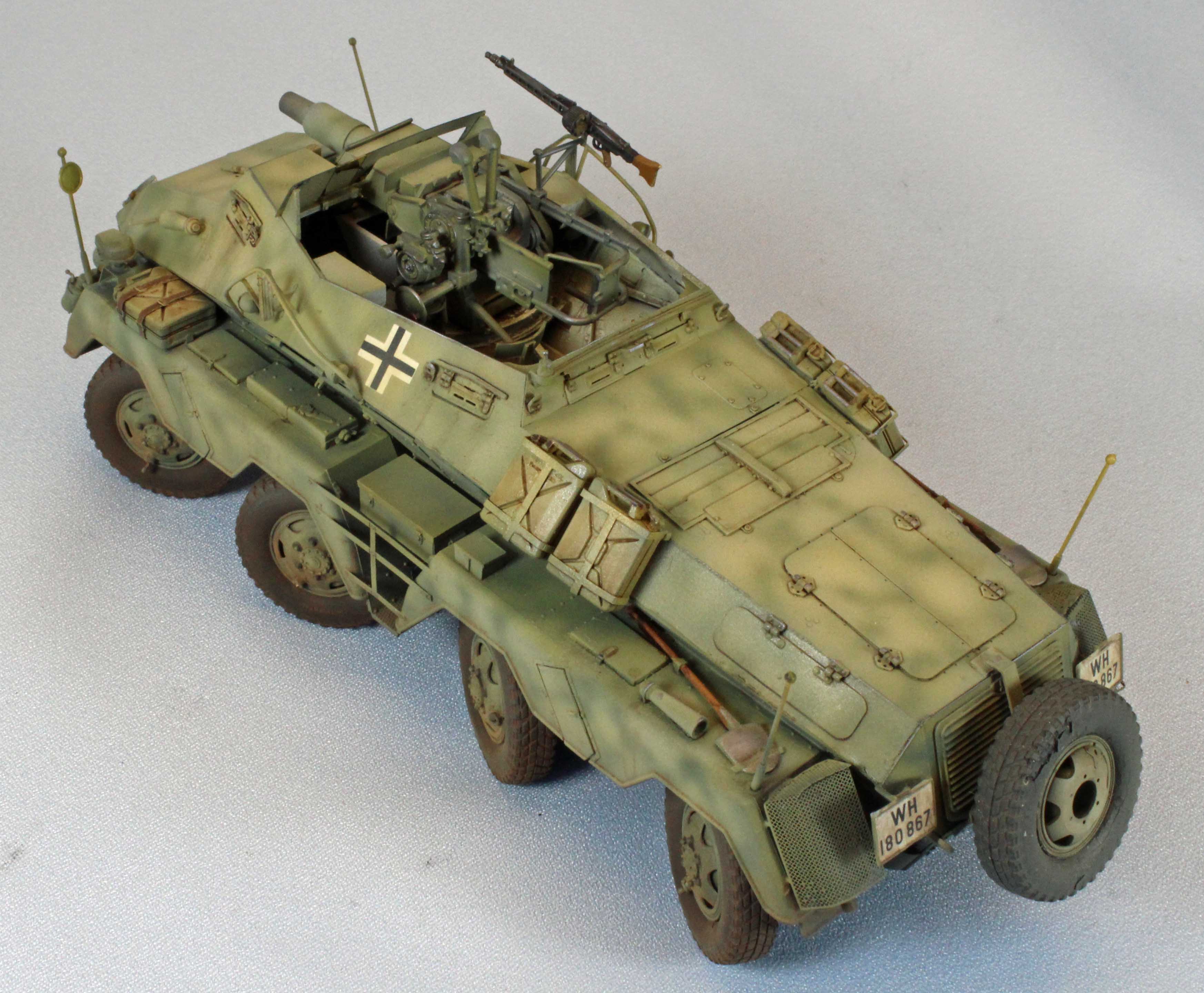
There is quite a lot of interior provided; including two driver’s compartments (one for each set of four wheels, fore and aft) and every hatch and view port on the vehicle can be modeled in the open or closed position. Still, with the large main weapon and the streamlined super-structure, precious little is visible on the completed model. Flipping the hull over uncovers an abundance of detail offered in the gear, axles and other odds and ends underneath and around the eight positionable wheels
Background
The heavy PanzerFunkwagen was a large but very fast and highly versatile addition to the German Army. The original 6 Rad (6 wheeled) versions were based on a 6x4 truck with an armored body, and were eventually replaced in 1937 with the 8 Rad versions. During the replacement, the Sd.Kfz. (Sonderkraftfahrzeug, ‘special vehicle’) numbers were carried directly over; differentiation is made by the addition of 6-Rad or 8-Rad in the vehicle's name.
These vehicles were used for the traditional cavalry missions of reconnaissance and screening. They scouted ahead and to the flank of advancing mechanized units to assess enemy location, strength and intention. Their primary role was reconnaissance, but they would engage similar or light units and at times attempt to capture enemy patrols. They appeared throughout the war in various guises and first saw combat in the campaign against Poland and in the Battle of France. Later, they saw use in both the USSR and North Africa, but extreme climatic conditions in both these areas proved too severe for the vehicle. On the Eastern front, adverse ground conditions immobilized 150 Sd.Kfz 232s during the first wet season of the campaign. The speed of the eight-wheeled cars made them the best scouting vehicles that Rommel had for long range reconnaissance across the wide desert territory in Africa.
Opening the box
The sturdy AFV Club kit box is relatively heavy, and filled to the brim with parts. The plastic is soft and in places, very thin, but I did not find any warpage or damage in shipping. There was some flash but nothing significant and what is there is limited to the smallest parts. A closer look will uncover very fine weld-seam molding on the upper hull parts. The nine ‘rubber’ tires are well molded and thankfully free of the sometimes-difficult-to-remove center line of rubber flash.
The contents of the box include:
- Aluminum, hollowed-out barrel end, packaged separately
- Main upper hull (two pieces), packaged separately
- 13 sprues in soft, light-tan plastic, packaged separately
- 1 single piece upper chassis protected in a hard plastic container
- 1 clear plastic sprue
- 9 soft black ‘rubber’ tires and shock absorber collets
- 2 small photo-etch sheets, including jerry can detail and floor grates
- 1 small sheet of decals with markings for two vehicles
- 1 20-page black and white instruction booklet with 44 steps,
including a 2-tone color, 4-view decal placement
and paint guide sheet
The Instructions
AFV Club thoughtfully assigns the same part numbers to similar parts, improving buildability. Not a big thing, but certainly appreciated.
The parts map is squeezed on to a half-page, resulting in part numbers that are blurred into solid blobs of ink. This is unfortunate since some of the parts in the instructions do not look or match those on the sprues (Part CC33, for example), and some parts (C44) are missing all together. It turns out that (plastic) Part CC33 is actually (photoetch) Parts GB1 and GB2. Both of those prominent parts are not mentioned in the instructions, but appear in pictures of the finished model, as do a small number of other parts (rear convoy lights, for example). Needless to say, I recommend that you study the photographs of the finished model carefully so you don’t leave anything off.
As with all open-fighting compartment vehicles, assembly sequence varies by modeler and I found that I had to move steps around in order to get everything done, a matter of personal choice and not a flaw in the instructions provided by AFV Club.
Things to consider before starting
The plastic used in the kit is soft; softer than what you might find in most other model kits. If you are like me and use a scalpel as your go-to hobby knife, you will want to take extra care in cleaning the parts before assembly. This is especially true with the many parts that are small and delicate - a deft touch is the key here.
While there are many, many [sprue ejection] plugs to remove, AFV Club engineers made the actual connection points very small, so cleaning the parts was a breeze.
The kit contains a lot of interior detail that will show through open hatches, including glimpses of both drivers’ compartments. While AFV Club chose not to provide a complete engine, they did include the bottom and back of one (which is the only areas that are visible), sporting pulleys, fan belts, engine mounts, etc.
As an open-topped vehicle, the build-it-all-and-then-paint-it approach won’t be the best way to go. To do a good job you’ll want to work this like an airplane model; build a little, paint a little, etc. It pays to plan ahead and proceed slowly. I skipped the main gun assembly after Step 28 and continued with the busy fenders and interior before stopping at Step 40 to prime and paint everything built to that point. I then glued the upper (fore and aft) sections to the lower hull before continuing with the rest of the build. I left the tires off until most of the painting and weathering had been completed.
The Build
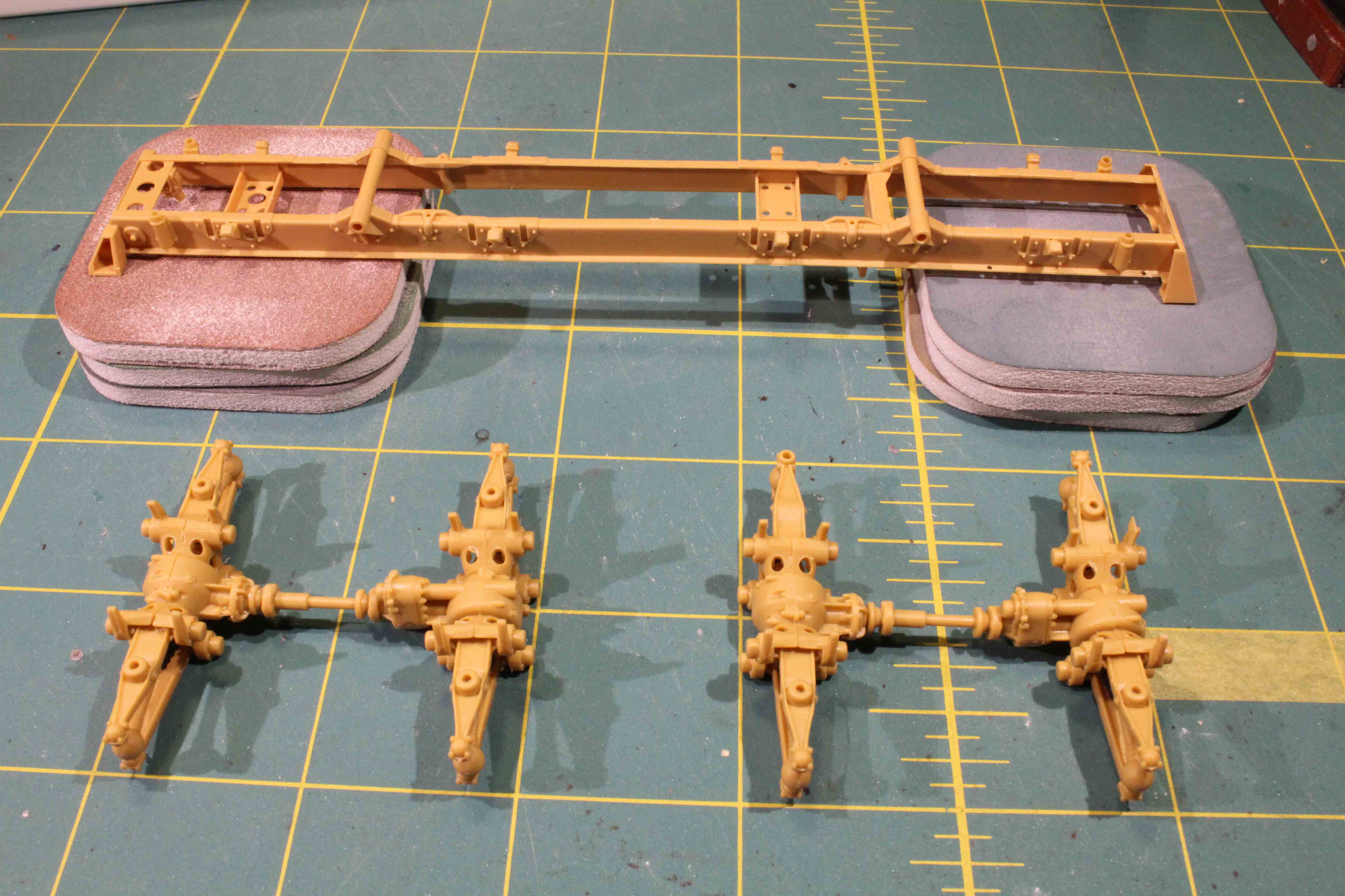
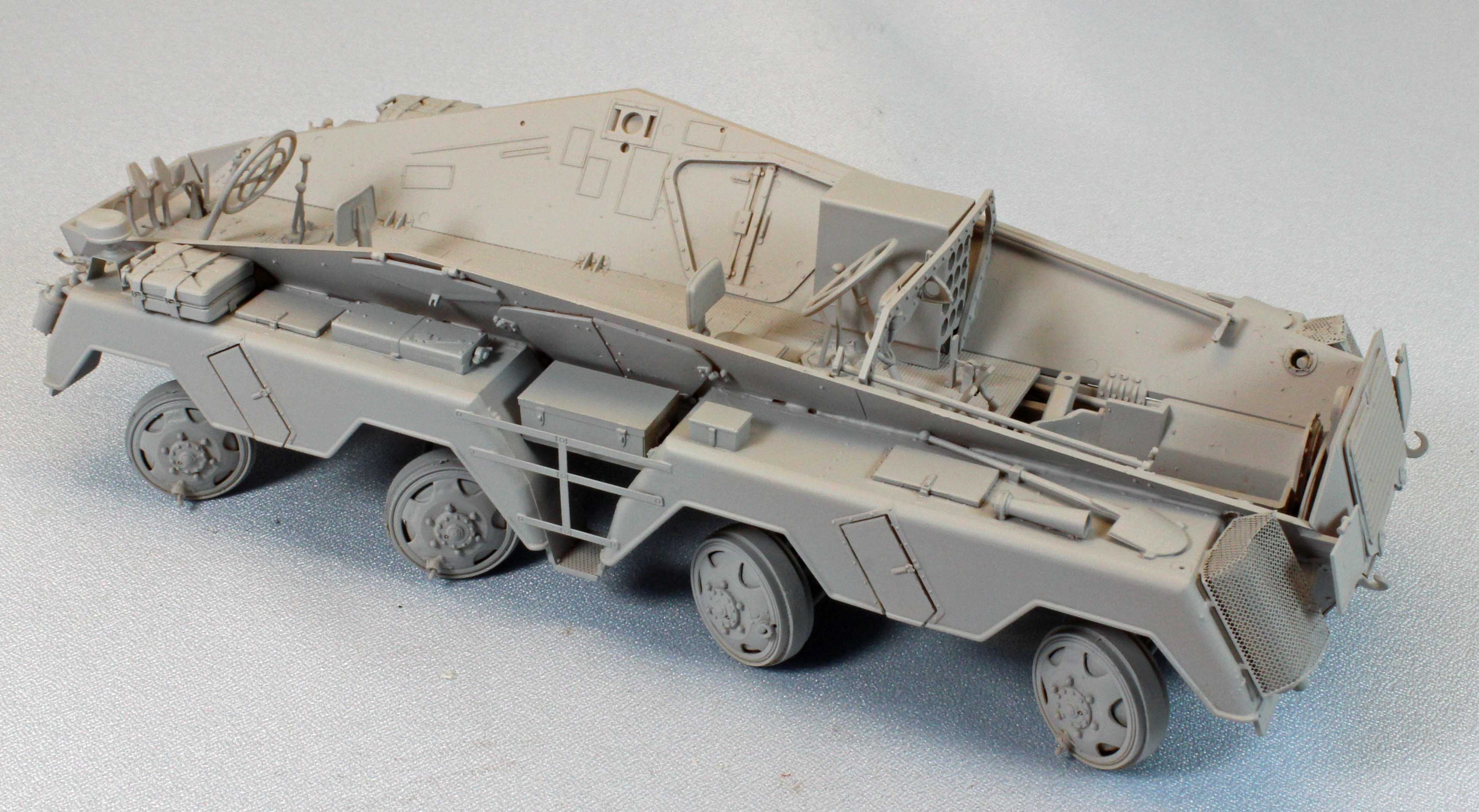
AFV provides the delicate chassis frame in a separate, hard-plastic container to protect it during shipping. Once the sprue plugs have been removed it’s easy to see why. Essentially, everything from the middle of the -233 down is attached to this one piece – it has to be sturdy, and in one piece.
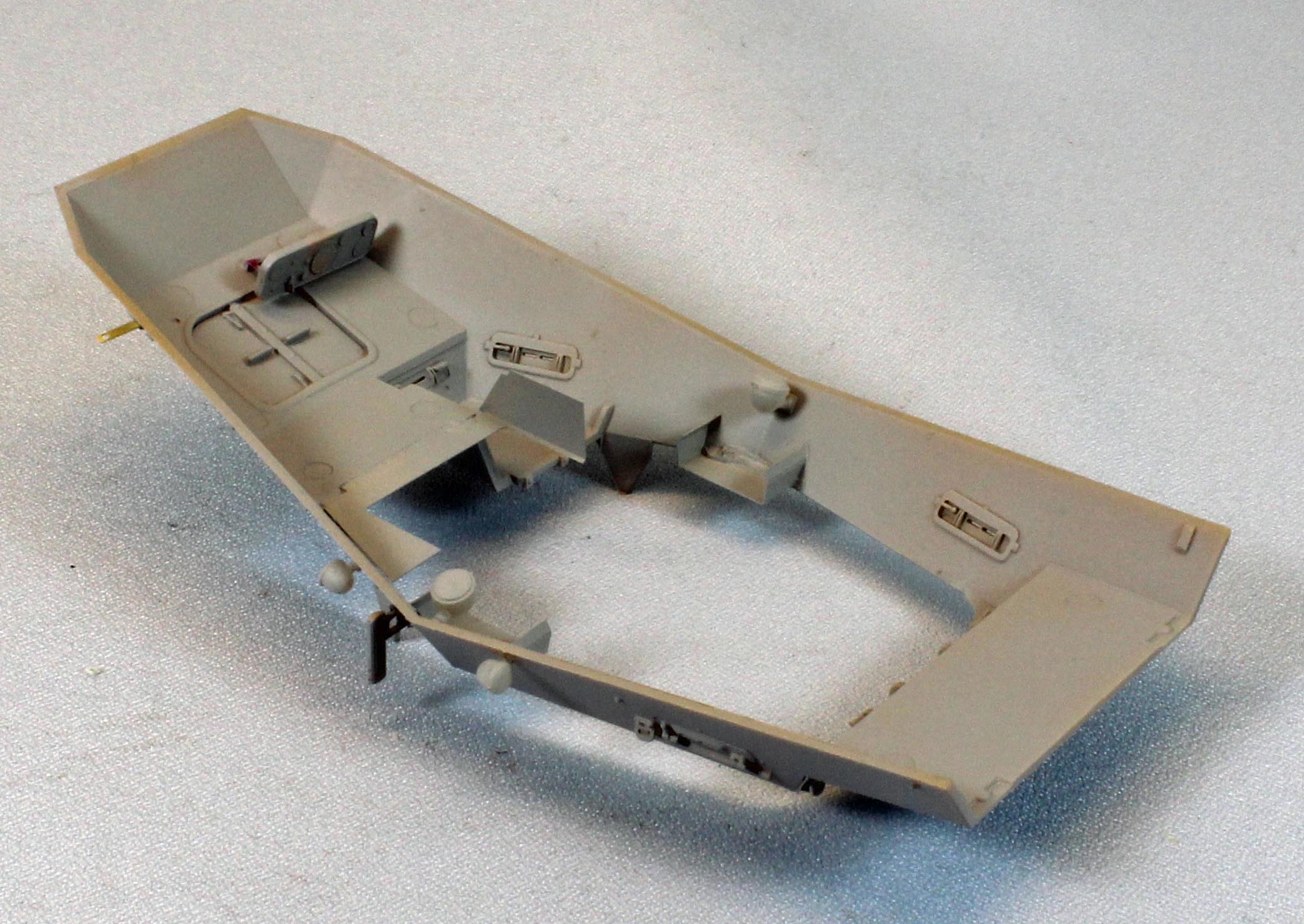
In Step 2, the instructions are vague about where to attach the two foot pedals (B33/34). You won’t know for sure if you’ve got them right until Step 12, when they will protrude up from the floor of the vehicle (long after they are dry and inaccessible). I crossed my fingers and attached them ‘there’. (They end up being barely visible so I don’t think you can go wrong either way). The pedals prevent you from turning the chassis over, however, without a making a jig of some kind (see image).
In Step 3 AFV Club provides eight ‘rubber’ dust covers for the two joints on each axle. This seems gimmicky at first, but works very well once the wheels are on - you can see how they keep everything in place if you decide to articulate the wheels. No glue is needed between Parts A10 and A21. Nice.
Assembly of the four articulated axles is tricky, but is easier than it looks. I laid part A35 upside down on a lump of clay, inserted parts A12 (they only go one way) and the axle assembly, and applied minute traces of thick Testors Cement (Black bottle) around part A35. I then held one of the two A13 parts and closed the assembly with part A34. I then carefully pried the assembly slightly open again and inserted the second part A13. Once you combined each axle into pairs, Steps 4 and 5 bring it all together. If you’ve done everything right, you are rewarded with an absolutely perfect fit throughout.
In Step 17 I came across the first fit issue that wasn’t entirely of my own doing. I wanted to model the rear engine hatch closed, but the hatch framing (Part C22) did not seem to fit into where it was supposed to go. I taped the front and rear upper hull parts to make sure I had the rear opening well-defined, and two protrusions on the interior of the hinges caused the framing to stand proud of the surface (see image). Removing the plastic behind the hinges solved the problem. I suggest that you fit the hatch framing and hatch to the rear of the vehicle before attaching the driver’s seats, steering wheels, etc., so they have a fighting chance of not being snapped off in the process.
This is where things get tricky. While the wheels can be orientated just about any way you want, they are not meant to be movable once installed. Once you decide how you want them pointed, you will be gluing them permanently so it is important to make sure that each pair (front and back) are reasonably parallel, each wheel is at a right angle to the ‘ground’, and all wheels are touching the ground.
The -233 had three primary wheel positions; turning at slow speed, turning at higher speed; and in-line. For slower speeds, the forward two wheels on each side acted together but independently from the rearward two wheels. For example, when making a left turn, the two forward wheels on the left side are canted outward and the two rearward wheels are canted inward, their partners on the other ends of the axles following suit. For turning at medium speeds, the two forward wheels on each side turned but the rearward wheels remained in-line. Additionally, in a slow, tight turn, the front and back axles were turned rather significantly, while the wheels on the inner two axles not so much. I chose to model the first position (slow turn) since it would expose and accentuate the detail in the lower chassis.
To make sure things went smoothly; I attached two wheels at a time using a cross-pattern approach (left-front pair, right-rear pair, left-rear pair, and right-front pair, and weighted the chassis while the glue dried. This insured that all the wheels touched the ground evenly, leaving each pair to completely cure before attaching the next pair. Once I attached all the stabilization rods and other hardware, I found each wheel to be relatively sturdy and would hold up to attaching the tires separately, after painting and weathering.
The detail of the lower chassis, once assembled, is a little breathtaking. AFV Club has set the bar here for 8-wheeled RAD armored cars. Bravo.
From here on out everything is upper hull and detail. The upper hull is separated into two sections, fore and aft. Both are studded with detail inside and out, and most of the inner detail is hidden on the finished model unless you leave the hatches and panels open. I chose to paint and weather the interior just in case, which dictated the assembly sequence moving forward.
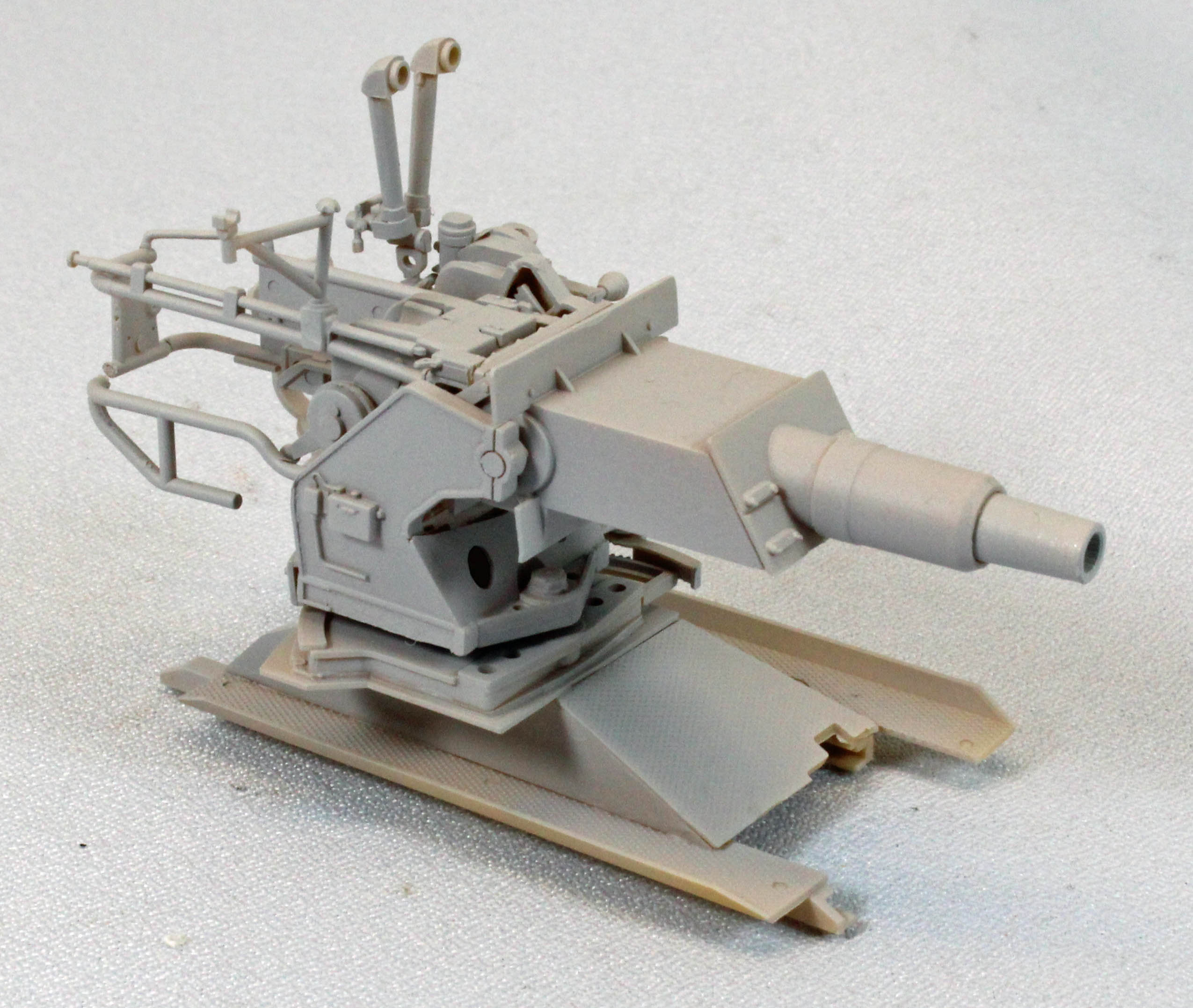
After attaching several interior parts, the instructions curiously pivot to the main gun assembly, which AFV Club has smartly designed as a single module that can be assembled, painted, weathered and dropped into the top of the completed vehicle.
Consequently, I deferred Steps 21-27 and continued with the upper hull and fenders.
The fenders on the -233 are covered with equipment and detail; a prominent feature of these early armored cars. I left the four nicely detailed Jerry Cans off for painting and weathering separately, but otherwise attached everything else. The cans are held in place by two types of delicate photoetch brackets that look harder to form into shape than they actually are.
Unfortunately, assembling and attaching the eight smoke dischargers on the front fenders is a lesson in patience - the design lacking in several areas. First, I recommend waiting to attach the tiny triggers on top of each canister until after they are on the fenders, so you can line them up. I had to position and reposition the canisters repeatedly, causing me to discard the PE parts and making a general mess of things.
The reason I had to reposition the canisters repeatedly is because they appear to be slightly over-scaled to the area they fit into. No matter what I did, the inner-most canister on each side prevented a solid fit of the fender up against the hull side, requiring some surgery to insure a clean fit. Locator pins with matching holes or slots would have helped in the positioning of these canisters.
Ironically, there are several positioning holes on the same fenders to receive detail in Steps 30 and 33 – but no mention in the instructions to open them even though AFV Club has thoughtfully pre-drilled the holes half-way through on the inside. The fit of the fenders to the superstructure was not as good as it could be. You have to choose between having horizontally-level fenders or gaps along the top where they meet the side of the hull. Fortunately, the inward-sloping sides effectively hide any gaps that appear along the super structure when all is set. Still, purists will want to fill those areas if they appear. In Step 33, there is a small lip on the front of Part D16 that cause it to stand proud of the surface of the fender, exposing the two (male) posts that go into the (female) holes. I can’t find any pictures that show that area very well, and it looks wrong to me, so I shaved off the bottom of the lip so the part would seat flat on the surface.
Continuing with the upper hull, the position of the front headlights in Step 36 will prevent access to the smoke canisters for painting and weathering, so I left them off for now, but opened the holes they went into. In Step 38, Part CC33 in the instructions is not what the actual part looks like; in fact, looking at pictures of the completed model online, the proper parts here are from the photoetch sheet (Parts GB1 and GB2). I’m not sure what happened here?
There is so much detail being added in Steps 36-40 that I decided to concentrate on the interior so I could paint everything inside, attach the front and rear upper sections to the lower hull, and then continue with the exterior detail.
The fit of the upper front and rear sections to the lower hull was good along the sides and the front, but left a small, even gap along the back. I slipped a thin piece of card plastic into the gap with some glue, solving the problem.
Curious – AFV Club thoughtfully supplies PE inserts for the four (fuel) Jerry Cans, representing the weld-line that runs along the outside of each can. But for some reason similar inserts for six additional (spare) fuel cans are not included in the kit. If you want to use the extra cans (and you want all the cans to look the same), you will (either) need to find PE inserts for the six cans in your spare parts box, or do without the inserts on the original four. I relegated the six spare cans to my parts box and moved on – it’s a shame, since the cans are beautifully detailed with separate handles and pour spouts, and without the PE inserts there is a recessed weld line on them, which would be inaccurate.
Steps 21–27 focus on bringing the nicely detail main gun and base together. I encountered a fit issue in Step 22; the three part ‘rack’ behind the main gun comes together well, but Part AA23 prevented this assembly from attaching to the rear of the main gun. The three ‘female’ holes are visible, but they are partially blocked behind the edges of Part AA23. I had to perform some minor surgery to clear access to the holes. (Note: Looking through the unused parts at the end of my build produced a part that looks a lot like the ill-fitting AA23 part. It is possible that the instructions simply miss-numbered these parts, but I can’t tell since I can’t read the part numbers on the Parts Map.
Step 23: The two parts (AA19/20) that frame the gun (left and right) have ‘receiving’ holes that are too small for the job, and a plastic post that has to be removed before they will come together around the gun (see image). Departing from the instructions, I found that gluing these two parts to the base (Part AA22), then inserting the panel (Part AA26) from the front, and then attaching this assembly around the gun will work best.
While I applaud AFV Club for its commitment to accuracy here, the overall design of the gun is a challenge in terms of buildability.
Final Assembly
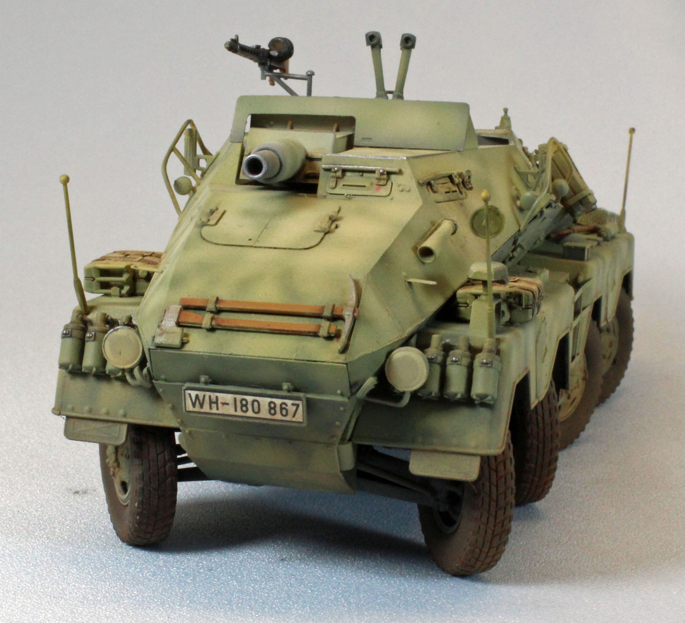
The final four steps (41-44) will have you attach a lot of subassemblies that would be better painted and weathered separately and attached after the rest of the vehicle is finished. I went through these steps with this in mind, leaving off the spare wheel, the PE armor plate (Part GA1) above the gun, the four fuel cans and their PE racks, and the MG42 machine gun before attaching everything else. The two vertical antenna and curved PE sunshade brackets were relegated to the spare parts box (after I snapped one of the antennas in three places!)
AFV Club offers three options for the hardware that mounts the spare tire on back. Each option has its pluses and minuses and I chose the first option since it did not rely on any PE and appeared to be the sturdiest of the three. As far as I can tell, however, the spare wheel does not firmly seat regardless of the option selected – there’s just no mating surface between the wheel and the bracket hardware. I sawed a ¼” round off the end of a plastic tube and glued that to the back of the wheel, then glued the wheel to the bracket and that seemed to do the trick.
I had some difficulty attaching the prominent bar structures (Parts N6 and N7) that protrude from the upper sides of the chassis. The ‘dimples’ that are meant to receive them didn’t want to line up with the actual ends of the parts. I did the best I could, using slow drying cement, holding them in place until set. A close inspection will reveal that (at least) one of the ends on each bracket sits out in empty space rather than fitting flush with the hull side.
But that was it - this little guy was finally ready for paint!
Painting and Finish
Open hull AFV’s are a challenge to paint. I found I had to approach the task in stages. Additionally, I wanted to use the hairspray chipping method to show wear and tear on the visible interior around the gun assembly. AFV Club provides two schemes, both in overall German Dunkelgelb. I thought I’d add a little flair to that in the form of mottled green.
Except for priming and pre-shade coats, I used Vallejo Model Air paints throughout. I’ve come to really like airbrushing this paint from a health standpoint, and I appreciate the amazing variety of ready-made colors available locally.
I started by applying a coat of (rattlecan) Krylon Flat Black Lacquer Paint/Primer for my dark, primer/pre-shade coat. Surprisingly, this low-cost solution sprays on easily and dries very thin and level – replacing a time-intensive task I normally use an airbrush and more expensive paint for. I use a dark primer coat to give the plastic and PE some grip, and to fill in the recesses - creating a shadow effect near the flat surface edges, and adding depth for the subsequent coats to come. I always let lacquer paint sit overnight in the garage to de-gas.
For the interior surfaces, I started by spraying a good layer of rattlecan hairspray over the (now dry) black pre-shade/primer. After blowing that dry I airbrushed a splotchy coat of Model Air 71.132 Aged White, allowing some of the dark pre-shade to show through around the edges. I let that cure for about an hour and then rubbed some of the white paint off using a stiff, short-hair brush, slightly damp with water.
While I let the wet surfaces dry, I painted the seats and steering wheels Panzer Aces 312 Leather Belt and the MG42 machine gun flat black and Panzer Aces 311 New Wood. Later I rubbed the ‘metal’ parts of the machine gun with Uschi’s Chrome Metal Polishing Powder to give it a ‘metallic glint’ before attaching it to the mount.
Next, I gave everything a couple of filter coats using Old Holland’s Warm Sepia Extra Oil paint, thinned with Mona Lisa thinner. I followed that with a pin Wash using Mig Dark Wash straight out of the bottle.
AFV Club uses a soft, slightly oily rubber for their tires. Normally with this material I don’t have much of a problem; I rough them up a little with sandpaper, spray them with Gunze Mr. Surfacer 1200, a lacquer primer, and then with Model Master U.S. Helo Drab (an enamel). Not this time. Even after waiting for each coat to dry thoroughly, the paint flaked off, right down to the rubber. When this happens, I usually move to Plan B: which is to lay down a thick coat of (acrylic) Future and start over. Instead, I decided to simply apply pigments directly to the rubber surfaces. I mixed up a slurry of Mig European Dust pigment and Mona Lisa thinner, brushed it on the tires, and when dry, rubbed it off using my fingers and stiff brush. Done.
I gave the exterior surfaces, wheels and the main gun a base coat of three Vallejo Model Air paints, applied in succession, to achieve a highlighted German Dunkelgelb. This was comprised of 71.025 Dark Yellow, 71.028 Sand Yellow and 71.075 Sand Ivory, applied in that order. Each paint is used to lighten the color underneath, yet still allow some of what’s underneath to show through. I then applied a camouflage coat of 71.096 Panzer Olive in a wispy, loose pattern.
Decals
With painting finished, I hand-brushed the surface areas that would be receiving decals with a coat of Future floor polish to give the decals a smooth surface to slide on to.
Once the Future was dry I went about applying the decals using the Red and Blue MicroSol and MicroSet products without any problems. Once the decals were dry, I airbrushed everything with a good coat of Future to set the surface up for washes and streaking. I skipped applying filters this time around since I felt that doing so would darken the upper deck too much – it was already dark enough. Once the Future coat was dry to the touch, I went to work adding a pin wash using Mig Dark Wash straight out of the bottle, and some streaking using AK Interactive Streaking Grime.
Finish
Once satisfied, I knocked down the shiny areas using Vallejo 70.520 Flat Varnish, followed by a coat of ‘road dust’ along the wheels and lower superstructure using Model Air 71.027 Light Brown. I also used this color to ‘tone down’ the decals a little. Finally, I carefully pulled on the eight tires, attached the MG42 up top and the spare wheel on the back; Done, done and done!
Conclusion
No doubt about it, this kit was a challenge to build, and to finish. AFV Club has a solid reputation for offering unusual, highly accurate injection-molded kits. This is especially true for this Sd.Kfz. 233, their second foray into German eight-wheeled armored cars.
That said, this kit is not for the faint of heart. You have to know what you’re doing, you have to have a lot of patience, and you need to know how to slow down. Sometimes there are no easily-defined connection points between parts, or they are absent altogether.
AFV Club chooses to focus on accuracy, and sometimes, in my opinion, this comes at the expense of buildability. Much of the detail is composed of tiny, exquisitely formed parts that would go together perfectly on a one-to-one, full-scale vehicle, but don’t necessarily translate well to a vehicle that is only seven inches long. Positive locator pins or holes would help a lot, as well as (common) assists found on other kits, such as interior ridges and/or insets that may not have existed on the real thing, but including them, out of sight, is no crime. They would be a real help on complex vehicles such as this.
Still, I was more than satisfied with the end result, and all that busy detail is awesome and looks great! The number of small parts, the complicated assemblies and the heavy use of photoetch leads me to recommend this kit to experienced modelers only. Go slow, pre-fit everything, and above all, have fun!
I would like to sincerely thank AFV Club for providing this kit for review, and to IPMS USA for giving me the opportunity to build it.