Reviews
Armor
Dragon M48A1
by Andrew Birkbeck
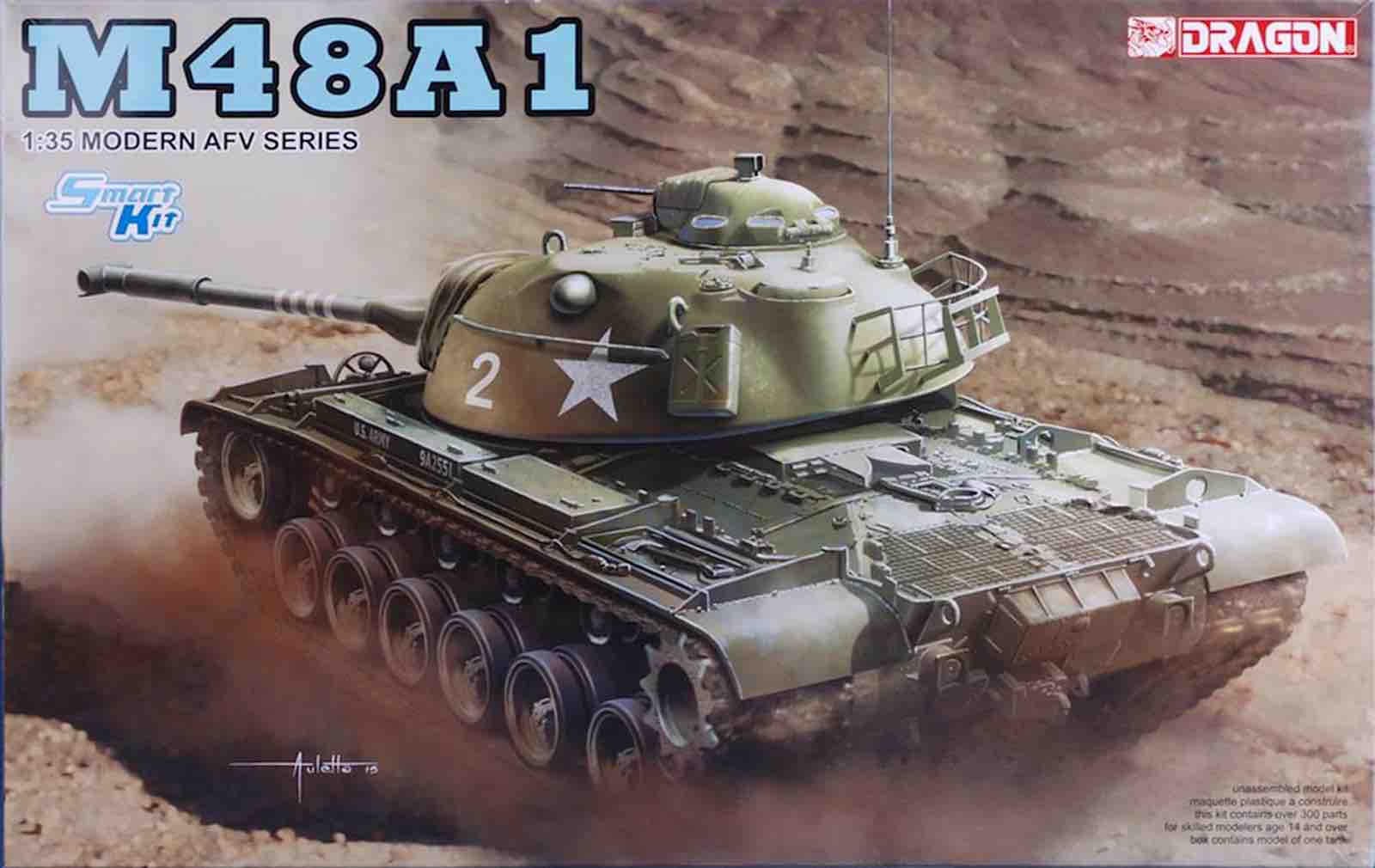 Model: M48A1
Reviewed by: Andrew Birkbeck, IPMS # 27087
Scale: 1/35
Company: Dragon
Price: $67.95
Product/Stock #: 3559
Website: Dragon
Product Web Page: View
Product provided by: Dragon
Background
The M48 tank was the third in a series named for the famous WW2 US general, George Patton. The first two were the M46 and M47 Patton tanks, and the M48, though looking similar to its immediate predecessor, the M47, was in fact a completely new design. It incorporated a 90mm main gun, and had a cast steel hull and turret, which was much more rounded than its predecessors, thus offering superior ballistic properties. Initial variants of the M48 had gasoline powered engines, but these proved to be poor performers, and so the M48A3 introduced a better performing diesel engine. Production of the M48 lasted from 1952 until 1959, with a total of just over 11,700 vehicles manufactured.
This is Dragon’s third M48, the first being an M48A3 Mod. B released in 2013 (kit 3544) followed by an M48A3 (kit 3546) in 2014. The initial offering lacked parts for the main gun mantle dusk covers, but the second kit, together with this M48A1 variant comes with rubberized DS100 parts for the mantle dust cover.
What's in the Tamiya Box?
- 10 sprues of gray plastic parts
- 1 small sprue of clear plastic parts
- 1 small “sprue” of tan rubberized DS100 plastic parts
- 1 fret of photo etched brass parts
- 1 length of twisted metal tow cable material
- 1 set of rubberized DS100 plastic tracks
- 1 sheet of water slide decals by Cartograph of Italy, with 6 different marking options
- 1 black and white instruction booklet, 6 pages, with 16 assembly steps
Under Construction
The instructions that come with the kit are typical of Dragon’s range of kits, being a bit on the “busy” side for my liking, so very careful study of each section is recommended to make sure the correct parts go in the right spot. The instructions have a handy sprue map, and as seems the case with all Dragon kits, there are lots of “parts not for use” areas marked, so again, make sure you are using the right parts for the job at hand! The plastic parts themselves are nicely detailed, without flash, and I didn’t find any sink marks or ejection pin marks in annoying places. Back to the instructions: there are a few sections that allow the modeler to choose from a couple of alternative layouts, such as the main gun mantle area. Be careful again to study the options thoroughly. I didn’t, and messed up, see later………
Construction begins as with many armored vehicle models, with the lower hull. First off we assemble the road wheels, which consist of FOUR parts each: inner and outer wheel hubs, plus inner and outer “tires”. I assembled the hubs, but left the rubber tires off until after painting. The drive sprockets too are four part units. Make sure you study the sprocket assembly diagram carefully to get the parts aligned the right way around, as it is possible to do it backwards. Once the wheels and sprockets are together, we move onto the assembly of the lower hull suspension, and again, check the instructions twice to make sure the correct parts are going in the right spot, with the correct alignment. Next come the return rollers, and I glued their hull mounting bracket, part C4, to the inner return roller part C3, which then was glued to the lower hull. I left off the outer return roller to allow for it to be painted separately.
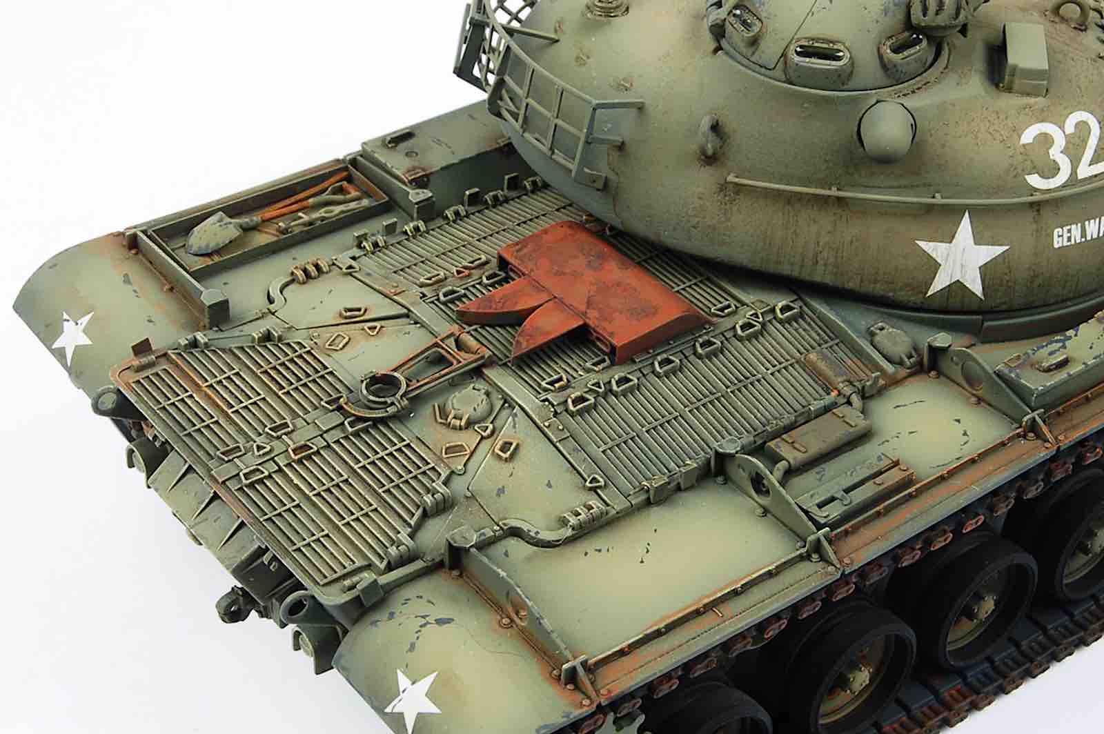
The assembly of the rear hull plate requires some use of putty to fill in a couple of notches on part D35, due to the multi version nature of this part. The rear engine deck parts need careful alignment so that unwanted gaps don’t appear. Test fit, test fit, sand/file where necessary, test fit again, and finally glue the parts in place. Next glue the main upper hull part, A1, to the lower hull unit, again insuring it lines up on all sides. I managed to get things aligned such that no putty was required. All that was needed was a simple sanding of the seam area where the two parts jointed together.
Dragon’s instructions have the modeler assemble the road wheel suspension arms to the assembled road wheels, and then glue these units to the lower hull sides. I deviated from the instructions by gluing the suspension arms to the hull side, and using a straight edged metal ruler, insuring the arms are all in alignment with one another. I left the attachment of the road wheels for later in the construction sequences. I also did not follow Dragon’s instructions, and left off the drive sprockets until later when I added the tracks.
As proof of how “all over the place” Dragon instructions can be, we now turn to the assembly of the turret gun mantle and the commander’s turret cupola. The clear plastic parts for the vision ports (H9 & H10) of the cupola I left off until the cupola was painted and weathered. Nothing at all complex involved with this Section, just follow the instructions.
Next comes the assembly of the tank’s fenders. Storage lockers, strengtheners, on board tools, all come together nicely. There are a number of photo etched brass parts utilized in this area, but nothing that should cause anyone any issues, as the PE parts are pretty simple, and are large enough to grip successfully with pointed tip tweezers. The front hull headlight arrays are also assembled and attached at this stage in the proceedings. I decided to keep the headlights off at this stage to avoid having them damaged during the rest of the construction sequences. I drilled holes in the base of the headlights, and affixed thin brass wire into the holes using superglue. I then drilled mounting holes into the headlight frames (parts J4 & J5) to mount the headlights at a later stage. Once the various parts were glued onto the fenders, the fenders were in turn glued to the hull sides. A little putty was required to fair the fenders in around the turret ring. I utilized an acrylic, water soluble putty called “Perfect Plastic Putty” by Deluxe Materials. Excess putty can be cleaned up with a wet Qtip. Thus I was able to get away with next to no sanding of the cured putty.
We now come to the assembly of the M48A1’s turret. Due to the use of the main upper turret shell part F20 in multiple variants of the M48, Dragon has the modeler carefully cut off some small parts of this turret shell for the M48A1, and also fill some holes not required for this variant of the M48. I then jumped straight to the assembly of the tilt mechanism for the main gun, so that I could get this installed inside the turret quickly, thus allowing me to glue together the upper and lower main turret shell parts, F13 and F20. Once the glue set, the seam line could be cleaned up, before moving on with the attachment of the exterior parts to the turret.
The assembly of the rear turret basket, which comes in five parts, proved a little tricky to line up. You really need three hands to do this easily, but I persevered, and got things nicely in alignment prior to attaching to the turret’s rear. And why did Dragon’s instructions have the modeler assemble this way back in Section 8, rather than with the rest of the turret? Probably for the same reason they had you assemble the commander’s cupola in Section 9: i.e. “who knows”. This is a slight annoyance with many Dragon kits I have built over the years, the occasional lack of logic in the assembly sequences.
The main gun in the kit comes in two parts, but not top and bottom, but rather front and rear. The gun muzzle and about one quarter of the gun tube is part F16, while the rest of the gun tube is part F14. Thus you have to be extra careful to line these two parts up in order to have a straight gun tube. This design does however eliminate the seam line which occurs on a top/bottom gun tube assembly sequence common on many other model kits. Once the gun tube was solidly glued it came time to attach the rubberized DS100 dust protector “canvas”, parts I4 and I1. This on the instructions is an alternative feature, and I have photos of many M48A1 tanks both with, and without the dust covers, so it is up to the modeler which to do.
And here is where disaster struck for me. The first part of the disaster involved putting the wrong dust cover on. For some reason as I built the model, I had a series of M48 photos I kept referring to, but most turned out to be M48A3’s. This variant has an accordion shaped dust cover at the base of the gun tube. And the Dragon M48A1 kit includes this on the DS100 “Sprue”. So silly ol’ me installed it on my gun tube. WRONG, the M48A1 has a different cover, which looks a bit like a shortened elephant’s trunk, part I4. But this error was the LEAST of my problems. For as usual, I assemble all of my models utilizing Tamiya liquid cement, in the green topped bottle. I swear I have utilized this to glue DS100 parts before, but something REALLY bad happened this time. Anywhere the Tamiya glue touched, cracks started to appear in the DS100 plastic, fissure-like cracks! The DS100 parts were literally tearing themselves apart before my very eyes. As I watched the cracks literally appearing before me, I grabbed some super glue, and put a drop immediately before where the cracks appeared to be heading, and this stopped the continuation of the cracks. I then doused the DS 100 parts “suffering” from this destruction with extra thin super glue. The cracking ceased. But the damage was massive cracks everywhere. The next day I took two part Epoxy Sculpt Modeling Clay, mixed some up into tiny balls, and with a wet toothpick, started to fill up the cracks. Then a damp Qtip was used to smooth and contour the Epoxy Sculpt. I then took the two other DS100 parts that I had yet to glue onto the model, part I1 and I5, the first being the main mantle dust cover, the latter being the cover for the Commander’s cupola, and super glued them onto the model. Result: no reaction, no damaged parts.
As I say, I swear I have used Tamiya green topped liquid glue before on DS100 parts without disaster. So I am not sure why this tragedy occurred with these parts. Has Dragon changed the formula for their DS100 plastic? I have heard recently of other issues with DS 100 plastic reacting badly to the harsher paint solvents such as lacquer thinner and even strong mineral spirits. Who knows, but forewarned is forearmed. Use super glue to be sure of avoiding damage! I now found myself with three main subassemblies: the hull with fenders attached; the main turret with gun barrel and dust covers attached, and the Commander’s cupola. Plus a bunch of road wheels with separate rubber “tires” and the drive sprockets. These were all primed with Vallejo’s black acrylic polyurethane primer, and left to dry for two or three days. I have found that if you allow the three day drying time (which is the manufacturer’s recommendation), the primer is very resilient.
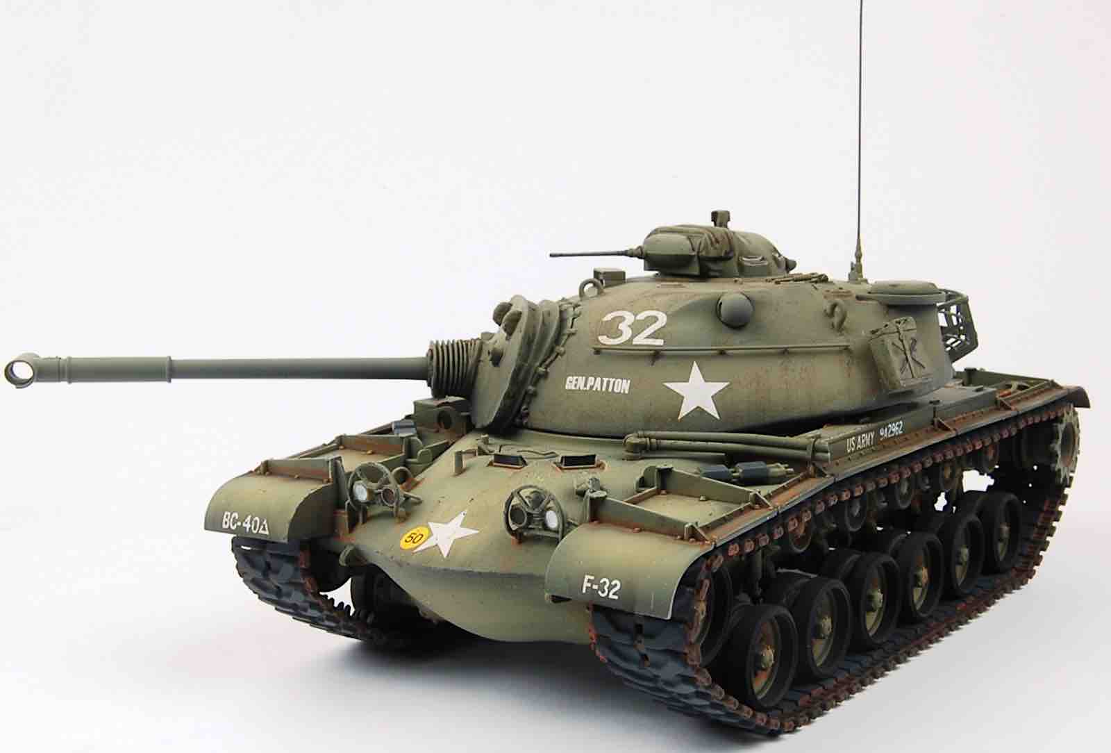
Next came the application of color, in this case overall green. My research indicated that at the time these tanks were in frontline US service, they were painted two different hues of green, one for Army M48’s, the other for Marine M48’s. Since it was the Army that utilized the M48A1, Army Green it was to be, and a good match for this is Tamiya XF-74 Olive Drab (JGSDF). Normally I would thin this with Mr Color Self Leveling (lacquer) thinner HOWEVER due to the earlier disaster with the DS100 parts I decided to be cautious and thin with Tamiya’s alcohol based acrylic thinner. I airbrushed all the sub assemblies bar the rubber “tires”, and when dry, I then took the base color, and lightened it with some Tamiya XF-60 Dark Yellow. This was then used to lighten various panels and highlights on the main parts. The tires were left black primer color and cemented onto the painted wheel hubs. Then after a day’s drying time, a few light coats of Pledge Floor Care Finish (aka Future acrylic clear) were airbrushed over all the painted parts and again, left to dry overnight.
The decals for the kit are produced by Cartograph of Italy, and are top quality. Everything is printed in register, the colors are opaque, and the decals commendably thin. There are six different color and marking options, or should I say markings options (as all the colors are the same, green!). Five are US Army, one is West German Bundeswehr.
- Option 1: 3rd Battalion, 35th Armor, Lebanon 1958
- Option 2: 4th Armored Division, W. Germany 1959
- Option 3: 3rd Armored Division, W. Germany 1960
- Option 4: 40th Armored Brigade, W. Berlin 1961
- Option 5: 40th Armored Brigade, W. Berlin 1961
- Option 6: “Unidentified Unit”, Bundeswehr 1965
I went with Option 4. The decals went on extremely well, utilizing the Gunze Sangyo two part decal setting solutions in the green and blue topped bottles, Mr Mark Setter and Mr Mark Softer. Mr Mark Setter, Blue Top, includes a milky white substance in its formula, which seems to act as an anti-“silvering” compound. You apply this to the model’s surface, then apply the moistened decal onto the Mr Mark Softer solution, and position the decal. Mop up any excess solution, and leave to dry about ten minutes. Then apply some Mr Mark Setter, to help the decal conform better to the surface. My one major objection to this kit’s decals were the vehicle serial numbers that go on each side of the tank, on the storage lockers. On my vehicle they say “US Army” plus a six letter/number serial. WHY Dragon/Cartograph couldn’t have printed these as one decal, instead of SIX individual decals, I don’t know. It was a real pain getting the six to line up evenly. Once all the decals were in place another 24 drying period was allowed for before I airbrushed multiple thin coats of acrylic clear over the decaled areas, both to protect them, and to blend them into the model’s surface.
The three main sub assemblies were then given an application of a dark brown “wash”, consisting of artist’s oil paint, thinned with Mona Lisa brand mineral spirits. This is the least harsh mineral spirits I have come across, yet it does the job just fine. The “wash” was applied to all the rivet detail, and the recesses, and left to dry overnight. The next day I took a series of Qtips, dipped in Mona Lisa thinner, and cleaned up the excess “wash”. I now left these subassemblies to dry for three days, to insure the oil paint had a lengthy time to dry.
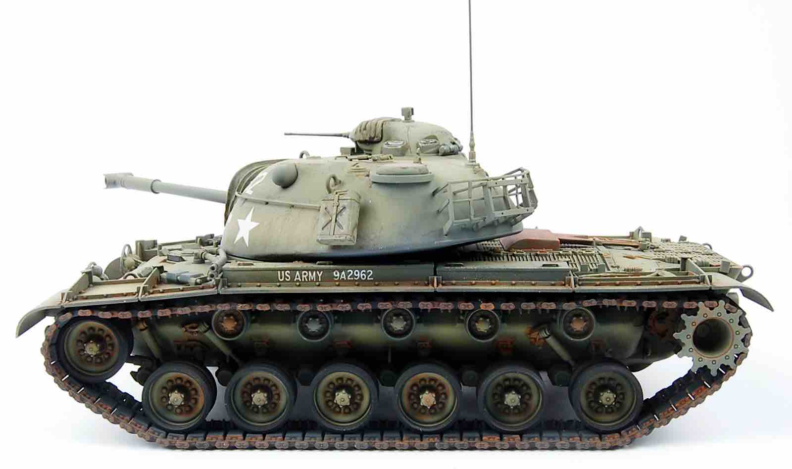
Once things had dried thoroughly, I painted the rubber portions of the outside return rollers a dark gray, and when dry, glued them in place on the model. Next I glued the road wheels in place. I had already glued the DS100 rubber band track together using SUPER GLUE, having learned from my earlier mistakes. The two track sections had been painted with Vallejo acrylic polyurethane dark gray primer both to seal the track material with a non-corrosive material, and to color the rubber sections of the track. I now took the track and mounted it onto the model. I slipped it over the front idler wheel and road wheels first, then took the drive sprockets, and applied glue to their sprocket mount on the hull side. MAKE SURE you test fit the sprocket to the mount first, as you will find that it fits perfectly one way, and not so perfectly the other way. Even though the sprocket LOOKS like it can fit on either way, clearly it doesn’t, so get it right! I then mounted the sprocket with track to the model, and clamped the sprocket in place to dry for 6 hours. Repeat on the other side of the hull. I found that the track was a near perfect fit for the vehicle, given it has so called “live track”, and thus no sag. Utilizing more super glue, I then super glued the track down onto the return rollers, to the idler wheels and to the sprocket, so it was firmly in place.
The very last item on the instructions, Section 16, shows the mounting of the track to the model. It also shows the mounting of two small wheels and what I presume is a track tension arm. These units exist on the earlier M46 and M47 Patton tanks. Looking at photos of the M48 prototype, the tension arms and their wheels are present. Looking at photos of M48A1’s in action, they are there in some photos, but not in others. They appear on photos of early M48A2’s, but then seem to disappear on later marks of the M48 completely. So I am not sure for the M48A1 if the wheels/tensioner arms were optional, or were deleted either on late production M48A1’s or when these vehicles went in for major overhauls later in their life? Either way, what is troubling is that Dragon’s instructions are VERY poor when it comes to how to mount these wheels/arms. I can’t for the life of me figure out a sturdy mounting platform for them based on looking at the parts, and looking at the instructions. So I just left them off.
With the tracks now installed, I airbrushed the three sub assemblies with multiple thin coats of AK Interactive AK183 acrylic “Ultra Matt Varnish”. If you want the matt-est matt finish around using an acrylic, THIS is the stuff. I didn’t have any AK Interactive thinner on hand, so I used Vallejo’s Airbrush Thinner 71.161, and it worked just fine. Once this was dry, I applied some “rust” to the metal parts of the tracks, using various shades of rust from the Life Color acrylic range. I applied some rust to other parts of the vehicle randomly “just because” as I think it makes an otherwise dull green vehicle more interesting.
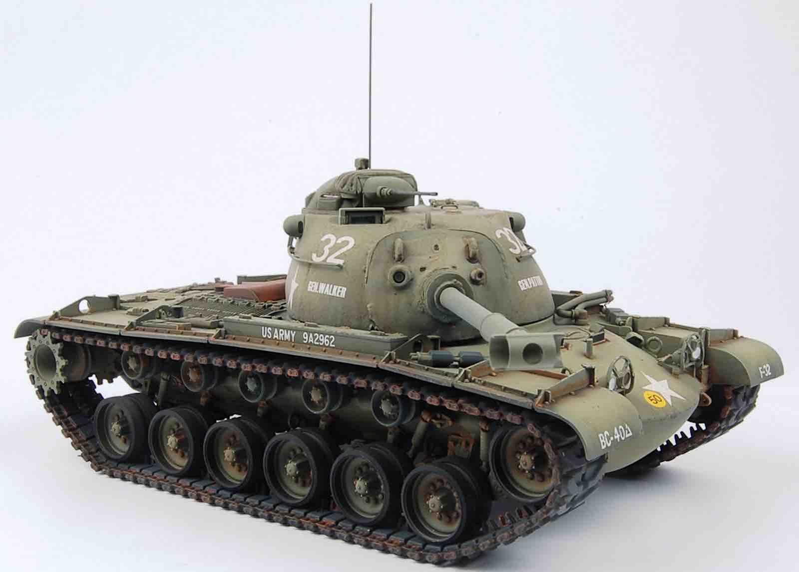
I attached the on board tools using Gator Glue then I attached the headlights, and I painted and drybrushed the cupola machine gun to give it a gun metal look. Then the three main subassemblies: hull, main turret, and commander’s cupola were mated together. Last but not least, the hull antenna was mounted again utilizing Gator Glue.
Conclusion
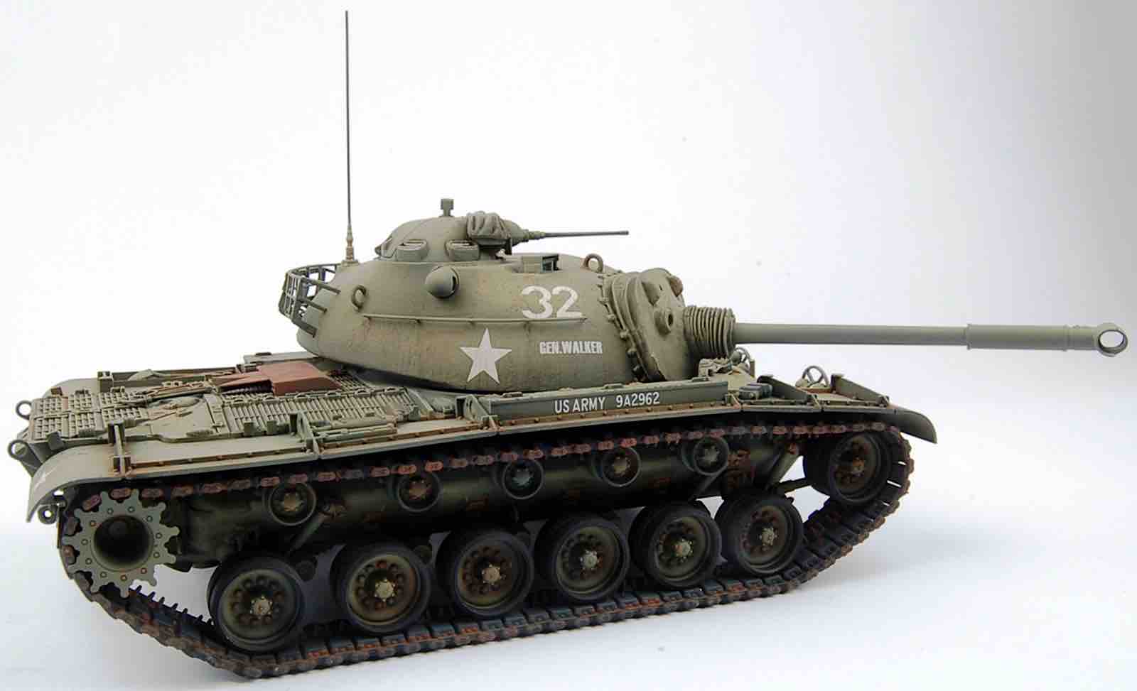
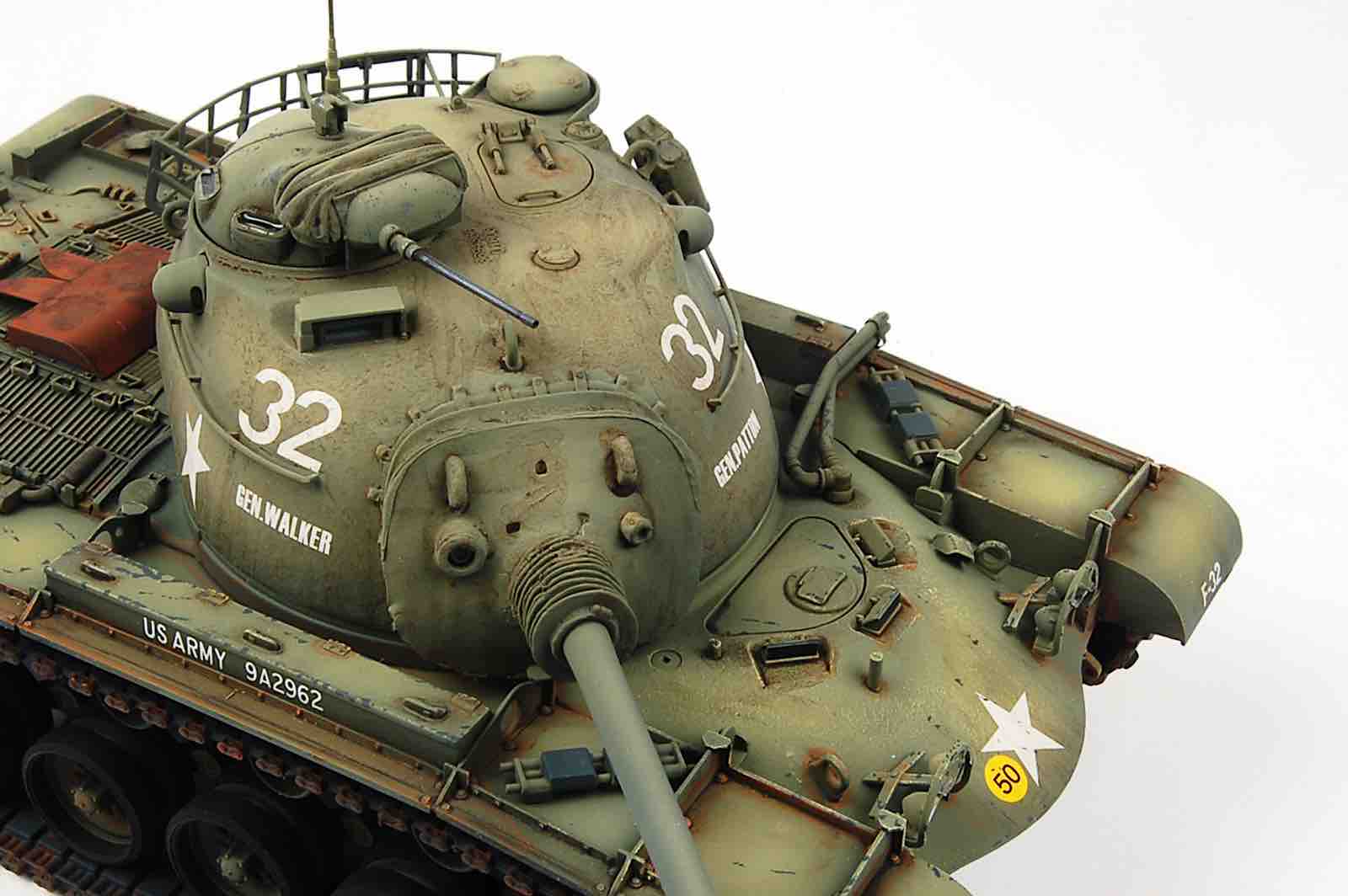
Overall this was a fun project, and Dragon’s M48A1 looks to be a very accurate model. If you carefully follow the instructions, and avoid using the “wrong” glue on the DS100 parts, you should be able to build this kit up into a super looking representation of this important Post Cold War warrior. My thanks to DragonUSA for providing IPMS USA with the opportunity to review this kit.
Photos