Reviews
Armor
Magach 6B GAL
by Eric Christianson
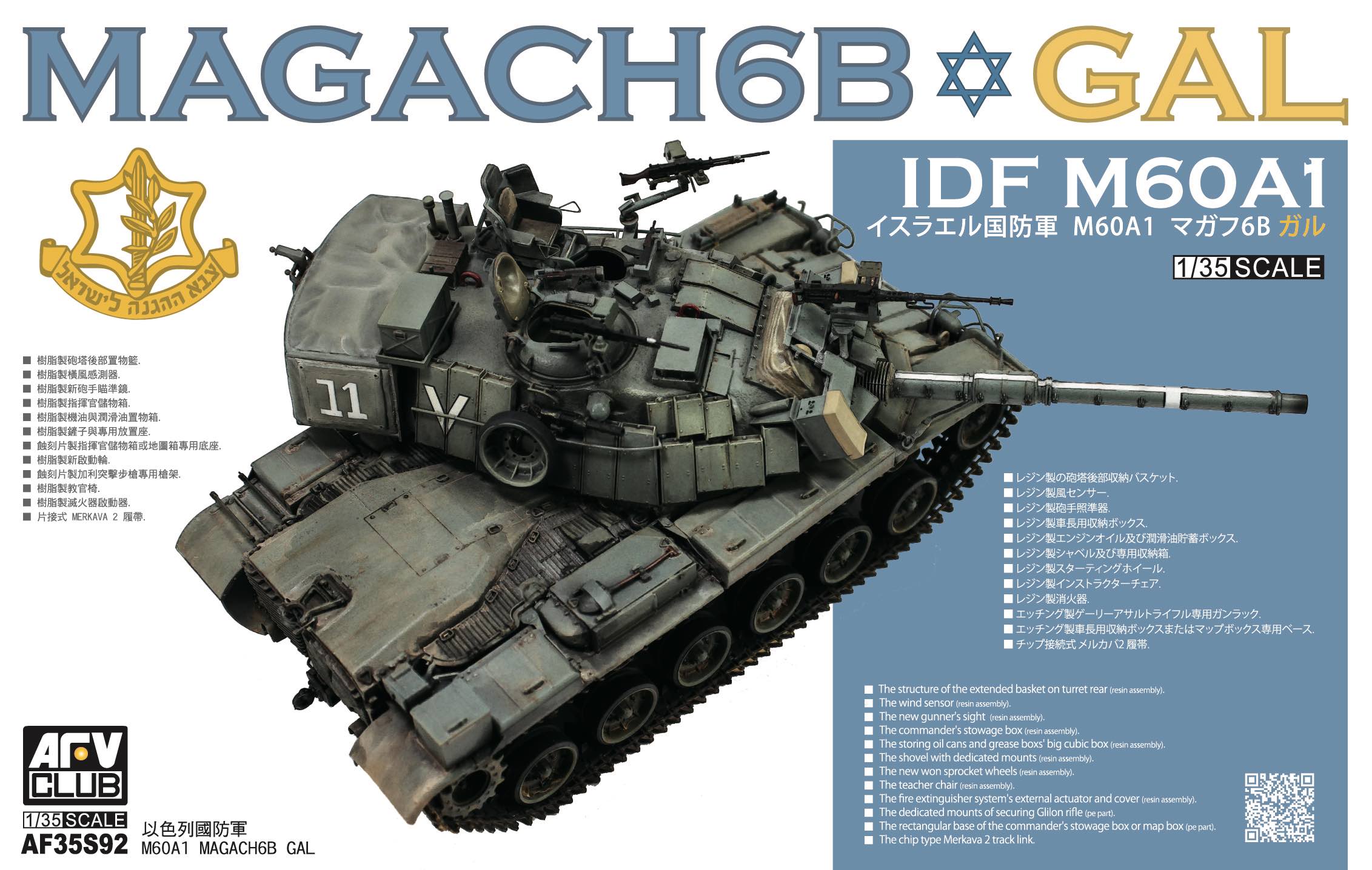 Model: Magach 6B GAL
Reviewed by: Eric Christianson, IPMS # 42218
Scale: 1/35
Company: AFV Club
Price: $124.99
Product/Stock #: AF35S92
Website: AFV Club
Product Web Page: View
Product provided by: Merit International
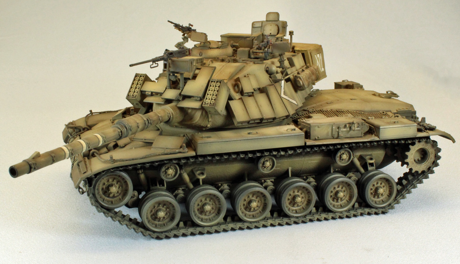
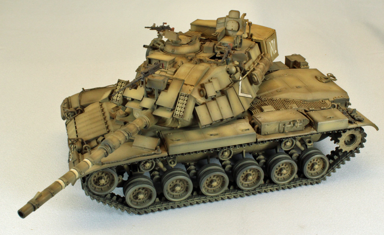
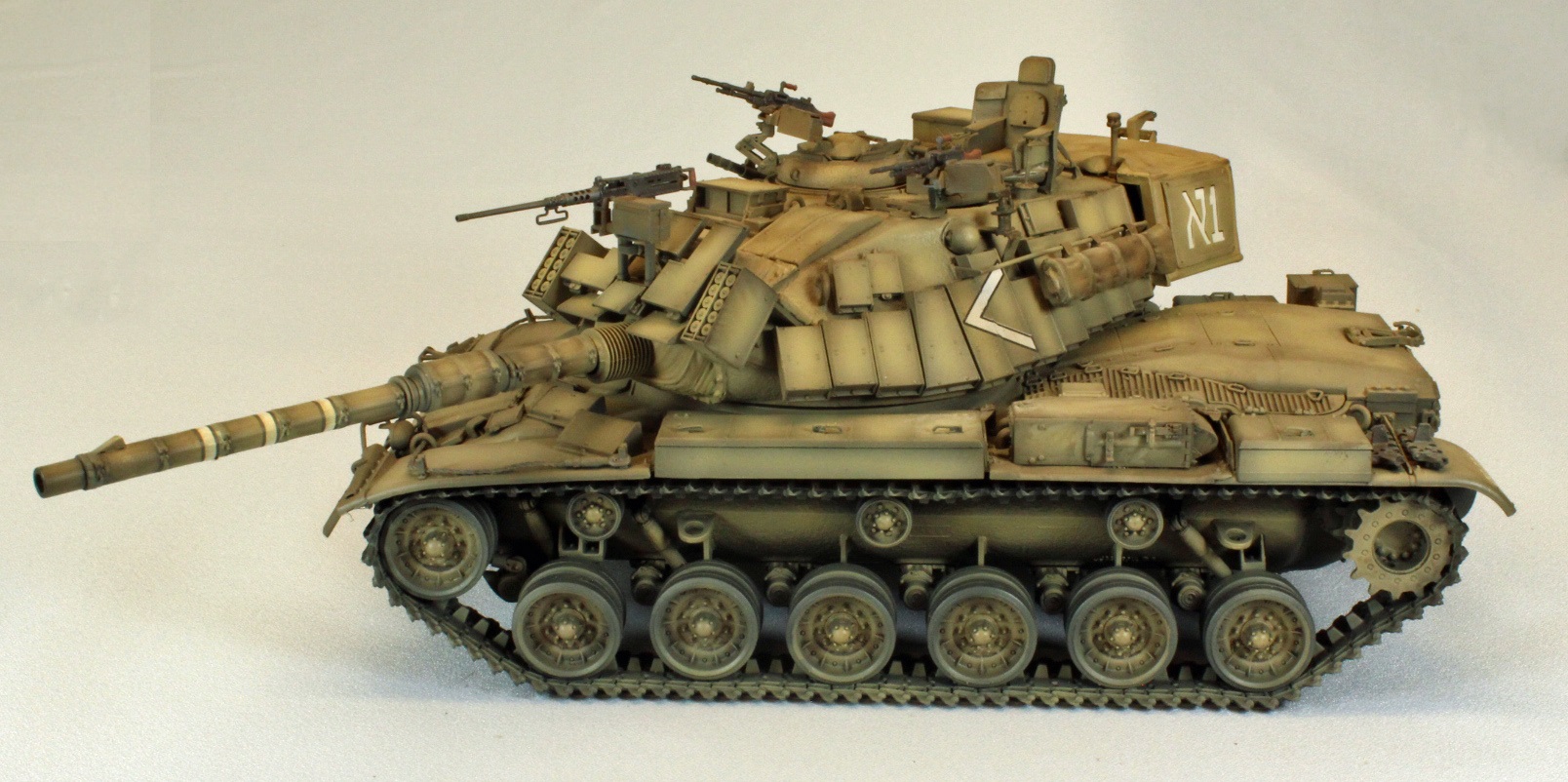
AFV Club has released yet another version of Israeli’s rework of the venerable American M60 Main Battle Tank. This time around we meet the ‘Magach 6B GAL’ – a version that, as far as I know, has only been reproduced in 1/35th scale with the help of an after-market Legend set. ‘Magach’, Hebrew for ‘battering ram’, has no less than six origins in Wikipedia, so I’ll let the reader decide where this moniker actually came from. Needless to say, these ‘re-wired’ M48 and M60 tanks proved to be equal to the task of filling the gap between earlier, British and WWII armor and the current Merkava armor types – the final conversion occurring in 2006.
Prior to the 1982 invasion of Lebanon (1982 Lebanon War), Magach 6 and 7 tanks were fitted with explosive reactive armor (ERA). Further upgrades included new belly armor, Merkava tracks, new fire controls, a thermal sleeve for the gun and smoke grenades, eventually resulting in the Magach 6b (Bet) and, ultimately, the 6b Gal Batash and equivalent Magach 7c Gimel models.
On a personal note, I’ve been waiting for this specific version of the Magach 6B Gal to show up in plastic for a long time, after having seen a similar build-up in the Legend Productions booth at the US Orlando Nationals back in 2012. The Legend aftermarket parts were mated with the old ESCI/ERTL Blazer M60A1… and it was just about the coolest AFV I’d ever seen. I had the Blazer in my stash, but Legend wanted too much for their resin set, so I walked away. Looking closely at what AFV Club included in this kit, however, it appears that my wait is over. If this isn’t the Legend set in the box, then it is something right up there with it.
Opening the box
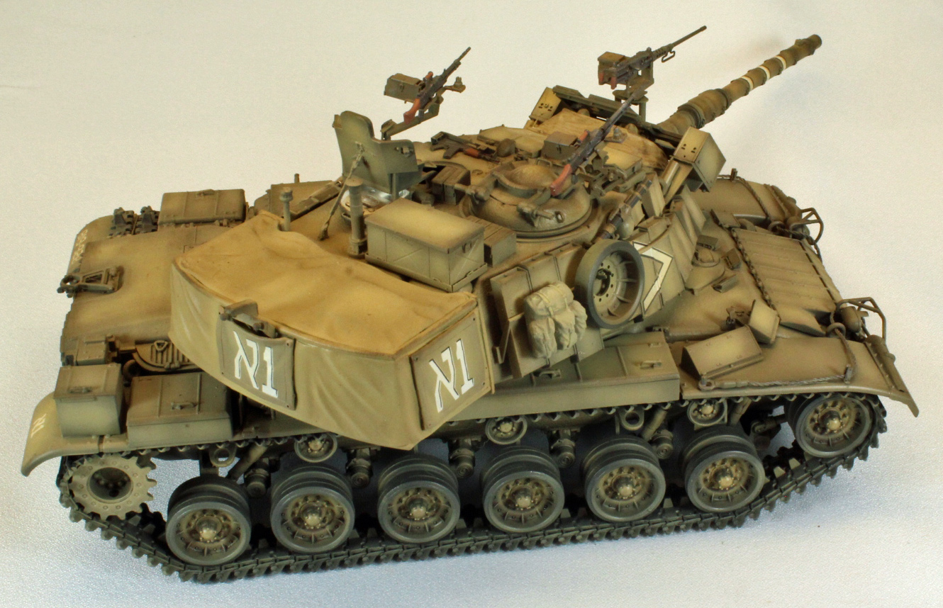
The large, sturdy AFV Club kit box is relatively heavy and filled to the brim with parts and extras. The plastic is soft and in places, very thin, but I did not find any warpage or damage in shipping. Unusual for AFV Club, there was minor flash on many of the small parts, but nothing significant. As per usual, the kit is replete with a variety of extras including at least five unused heavy machine guns and a variety of small arms, as well as extra fire extinguishers, grab handles, stretchers, etc., etc. There are also more resin parts than I’ve ever encountered in any mainline AFV Club kit. Along with replacements for the drive sprockets, there is a solid resin block representing the rear-turret bustle – handy, but not useful for those who would like to show some detail in the bustle, since it is covered with a fitted tarp. There is also a resin shovel and a complete, one-piece ‘observation’ chair that mounts on top of the turret, if you decide to model that particular version. While there are two turned aluminum parts that fit (on) the main gun barrel, the majority of the shaft itself is comprised of two plastic halves (with the ubiquitous seam-line). The sprues are molded in such a way to minimize shipping damage to very, very fine lengths of plastic that represent the railings along the sides of the turret. All arrived safe, without breakage, in my sample copy. There are two sets of wheels, including the accurate IDF versions as well as the original standard M60 set in the kit. Unfortunately, only the standard set are molded with separate tires.
The contents of the box include:
- 17 sprues in soft, medium-green plastic, packaged separately.
- 18 sprues containing 12 track light brown links each
- 17 resin parts, incl. commander’s chair, drive sprockets, turret bustle, track links, more.
- 2 turned aluminum barrel parts that mate with plastic parts.
- Lower hull, packaged separately.
- 1 bag of 14 rubber O-rings to assist with wheel removal (for painting)
- 1 length of string for the tow cable
- 1 rubber/plastic gun mantlet shroud
- 4 small photo-etch sheets containing mesh parts and small details.
- 1 sprue of clear parts containing headlights, lenses, and viewports, packaged separately.
- 1 medium-sized sheet of decals with markings for four vehicles.
- 1 24-page black and white instruction booklet with 42 steps, including three color pages showing (four) 5-view decal placement and paint guides.
The Instructions
The side-bounded instruction booklet, unfortunately, does not contain a list of unused parts – an omission which is compounded by the fact that the parts map is printed on one half of one page – far too small to read the numbers. In fact, it is difficult to even make out the shape of many of the parts. I would humbly suggest that AFV Club either use an entire page for a legible parts map, or re-task this half-page space for a more useful purpose. On the plus side, the instructions contain color call-outs for Gunze Sangyo (lacquers and acrylics), Humbrol, Revell and Lifecolor, and the decal placement instructions are supplied in beautiful, five-view CAD images. Also, AFV Club thoughtfully includes a short history of the Middle-Eastern conflicts and how the M48 and M60 MBT’s were employed throughout.
Sprues and parts are color coded in the instructions, so I was able to easily distinguish between like-labeled sprues.
Things to consider before starting:
The plastic used in the kit is soft; softer than what you might find in most other model kits. If you are like me and use a scalpel as your go-to hobby knife, you will want to take extra care in cleaning the parts before assembly. This is especially true with the many parts that are small and delicate - a deft touch is the key here.
Depending on what scheme you want to go with, there are some painting decisions to be made that will alter the flow of assembly – all noted below.
Finally, the covers that appear on the smoke dischargers in all the artwork were not included in the sample kit I received, nor are they found in the instructions.
The Build
The Lower Chassis, Running Gear and Main Deck
Curiously, the instructions begin with assembly of the three turret-mounted machine guns, normally relegated to the very end of an armor build – which is where I moved that particular task. I chose instead to begin with the lower hull and chassis, which comes together with separate lower hull that you add pieces to the top to result in a complete chassis. Overall, the fit of everything is spot-on and sturdy when complete.
That isn’t to say the lower hull is free of complexity. Right off the bat, in Step 4, AFV Club has made a gallant effort in designing the complicated front bogies peculiar to this vehicle type. I suggest that you (first) glue (C4/C5/C6/C7/C8 and C9) to the hull and leave that to dry overnight. That way you can slip things into their proper place without having everything fall apart along the way. I don’t blame AFV Club for this design – these tanks all carry this Rube-Goldberg-ian front end. Go slow.
In Step 7, the two tail-light assemblies (Parts 96) will not fit as shown in the instructions, leaving the lights hanging in mid-air, and the various ‘go-by’ lines provided fall in-between where the lights appear on the painting/decaling images. I ended using the rectangle box go-by’s and ignored the single lines – the result is closest to the painting diagram.
In Step 8, the wheels slip on to their axles with a very satisfying ‘chunk’ – telling you that they have reached as far in as they can go. Sure enough, the center gaps between each wheel pair line up perfectly – I assume this is due to a novel design using “O-rings” instead of poly-caps between each two-wheel assembly. This is the first time I’ve seen this approach, and it looks to be a real winner. Good job AFV Club.
Steps 9-11 include a lot of interior detail that ends up out-of-view on the finished hull, including an elaborate driver’s compartment and seat, as well as other odds and ends here and there. There is so much going on at the front of the hull on the outside that opening that particular hatch to reveal all this goodness seems to be wishful thinking on the part of the kit designers.
In Step 13 the multi-faceted upper deck starts to come together. AFV Club decided to have the modeler add the 14 grab handles separately – a fiddley task that, in the end, looks good, and is worth the effort. Thankfully, they even threw in a few spares to replace all the parts that fly off your tweezers to who knows where.
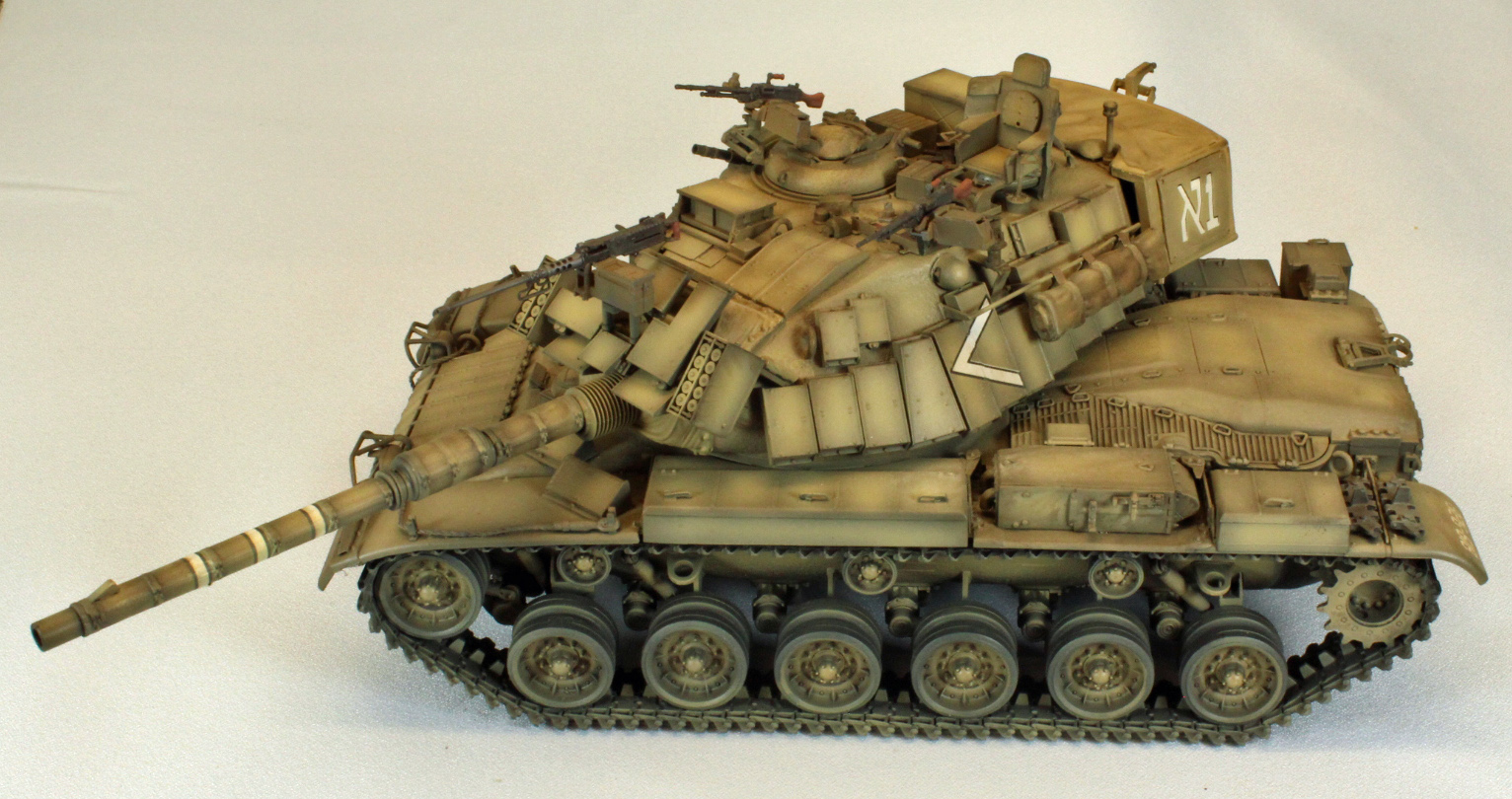
The Track
AFV Club provides individual-link track on 18 sprues of soft, medium-brown plastic. Each link has four sprue connection points, and unless you own a pair of GodHand sprue clippers, a significant amount of clean-up work lies ahead of you. Luckily, I do own a pair of these wonderful shears, and was able to carefully remove each link from the sprue and attach them together with only minor cleanup here and there. These clippers are worth their weight in gold (which is about what they cost)! There are 216 links in the kit, 108 per side, but I pushed 96 links on each side into a single run using Testors ‘Black Bottle’ liquid cement. (Note: There are two nice resin links to use on the left-rear fender, so you won’t need to save any of these links for that purpose - see Step 20) I let each track run sit for about an hour before I picked it up and wrapped it around the drive sprocket, wheels and return roller, connecting it just under the real wheel on each side. Love it.
The Fenders, Deck and ERA armor
The design and fit of the three-piece fenders (two on one side, and a single fender on the starboard side, is poor. There are several alignment tabs on each side, but they do not exactly line up with their respective slots without sitting directly on the track. Do not fret about the center sections appearing to (not) line up – there are storage lockers on each side that hang over the fender edges in those areas. In the end, the fenders sit correctly over the track, even if you don’t employ all the guide holes.
Two, 4-piece exhaust encasings come together in Steps 17 and 18, with one of them formed in resin. This is another head-scratcher – why? It complicates assembly and does not bring any benefit to the build. Also, pay attention to the diagrams – I found a way to attach the end pieces incorrectly on both assemblies. I suggest using the image in Step 19 for assistance.
In Step 19, Assembly A has three bolts that sit directly atop three identical bolts on the hull, which causes the assembly to sit a little crooked when viewed from the rear. This was remedied using a small shim placed between the sets of bolts.
In Step 21, Parts B17 have two pre-drilled holes in each of them, yet do not receive any parts that I can find in the instructions nor in photographs, so I filled them in. Parts W8, on the other hand, do not have holes drilled for them, so I created those as best I could.
Parts B28 and B30 square off the front end of the fenders. The locating hole on each side, however, (may) be off depending on how the fenders ended up, like on my build. I had to remove the (male) pins and reposition the two parts, then fill in small gaps behind them with Perfect Plastic Putty to square everything up properly. My guess is that this problem was to due to the issues I had with aligning the fenders.
At the top of Step 23, AFV Club runs you through their ‘tow-cable challenge’ again, using black thread and solid plastic tow-ends. After coming at this from several wrong ways over the years, I’ve settled on the following procedure: First, after measuring and cutting the thread into two 8mm pieces, drag the thread ends through thin CA glue and immediately dip them in CA accelerator to keep the ends from fraying. Next, very carefully drill out the ends of the four buckles, graduating up to as large a drill bit as you can fit inside the cable ends – you’ll need the room. Next, coax the thread through the four stanchions (two on each side) and down to the towing pintles on the hull. Finally, use the strongest white glue you have to attach the thread ends to the buckles, and leave to dry. Once dry, attach all four ends to the appropriate stanchions/pintles, and dab white glue here and there to force the string cables to adhere to the shape of the deck surfaces.
The Main Gun and Turret
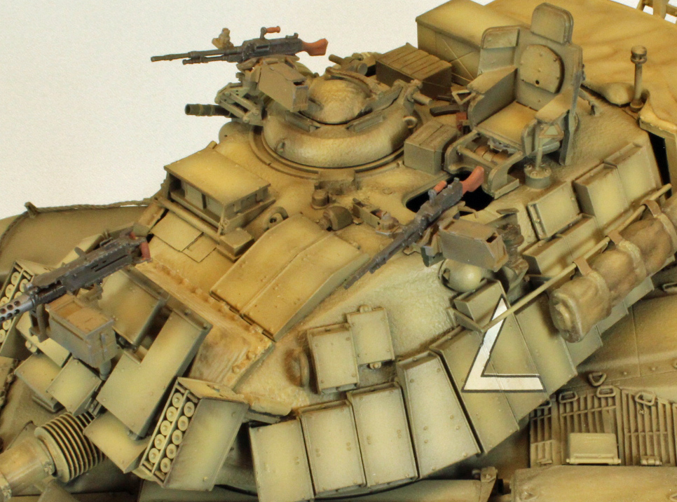
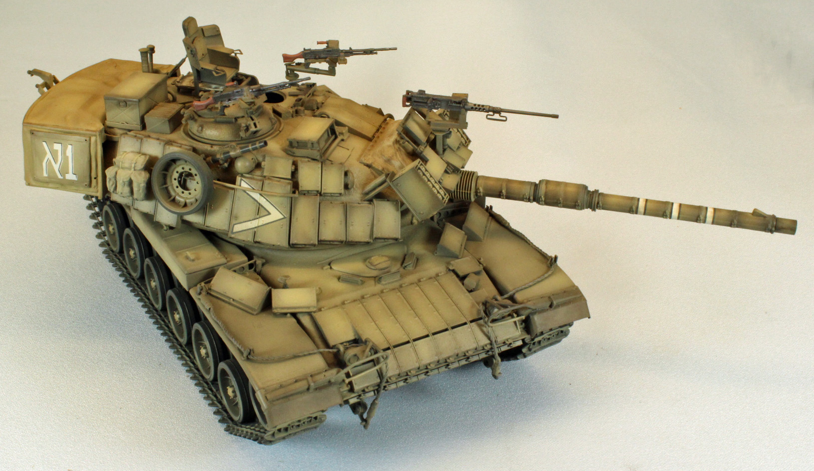
The rest of the build (Steps 24–42) bring together the beautiful, and busy, turret. Like most modern combat vehicles, the Magach turret is loaded with detail. AFV Club gives you the option of adding an instructor’s chair up top, situated over the open loader’s hatch. The busy-looking chair is nicely molded in resin as single piece, once you remove it from the substantial mold block it sits on.
The turret itself is made up of two nicely molded parts using an upper/lower clamshell design connecting along a natural seam line. As mentioned previously, the outside is beautifully textured, even if you don’t end up seeing much of that once you apply all the detail on top.
There are several holes that need to be drilled out before assembly, although in the end I did not use any of them (and had to fill some up). The way the two halves come together around the main gun is tricky: the gun is partly inserted, and partly trapped between the halves, a procedure that involves no less than three different articulating assemblies (E37/E36/E19, E4/E65/E3, and A2/A3). I strongly suggest that you dry-fit all of these parts, with tape if necessary, before committing glue to anything. To AFV Club’s credit, everything fits perfectly once you get it all together. That said, after all that work, once the poly mantlet cover is firmly in place, the gun isn’t going to move anywhere, regardless of the articulation built into it - it sits rock-solid horizontal. Even more so later on, when a large, flat piece of ERA latticework is fitted down over everything.
Note: The image on the right-hand side of Step 26 incorrectly shows the base of the protruding barrel as a stepped-down affair, after attaching the poly mantlet cover. In fact, the wider base of the barrel sits flush with the cover. Based on the image, I thought I had erroneously attached the barrel backwards – I did not - the image is inaccurate. Don’t bother correcting two prominent ejection pin marks on the top of Part A1 in Step 28. Those marks will be completely covered by Part E40 two steps later.
The most challenging part of the turret involves the placement of three, long railings along the sides of the turret (parts V35, V40 and V41). Inexplicably, while there are beaucoup placement marks along the sides of the turret for other things, there are none for these three critical pieces - critical since everything else fits under and around them. A simple, scale side-view of exactly where these go would have helped tremendously, along with soft placement marks. In fact, these prominent bars, which appear above all the ERA detail, are not even included on any of the side-view images in the instructions or decal/paint images. I placed them as well as I could using the three-quarter, oblique images in the instructions. As a result, I had to find places for two of the ERA boxes that would not fit in their intended location, and I had to make extra room for two others by shaving off parts of other, surrounding pieces. Your experience (will) be different, because the exact placement of the bars is so vague.
There are two prominent smoke dischargers, one on each side of the main gun, that come together in Step 36. The images of the two assemblies (E and F) are missing the two halves of the main casing (2x2 Parts U-26). Everything fits only one way, so it is easy to figure out what is what here.
Step 35 introduces a painting challenge. Part U14 supports a latticework of ERA that fits as a single piece over the main gun, directly onto the mantlet cover. Bracketing this are the two smoke dischargers, one to each side. Since I wanted to paint the mantlet cover a different color than the surrounding area, I decided to leave the entire assembly off, and paint it (and everything that goes on it), separately, attaching the assembly at the end, before weathering.
In Step 37, I could not fit Part V37 into V33 with any confidence, the combination being uneven at best. Instead, I pushed Part V37 into the (already in-place) Part V36 and carefully applied glue to the top of V37. I then dropped the V33 assembly in place as shown in Step 38.
Note: The covers that appear on the smoke dischargers on all the box artwork as well as the decal and painting images, were not included in the sample kit I received, nor are they found in the instructions.
The Instructor's Chair
The large instructor’s chair is provided as a single piece of resin, with an additional resin turnbuckle attached to the back, to anchor it to the hull. The bottom of the chair is made of two plates that are supposed to sandwich around the hull rim of the open loaders hatch. The connection between the two plates comprises of (2) scale-size bolts – meaning, by the time you separate the chair from the resin block, and then work the two plates around to point the chair forward, the bottom plate has long since sheared off and is rattling around inside the turret. In other words, not a great design here. Thankfully, the chair looks pretty good without the lower plate, so keep all this in mind when you are oh-so-carefully removing that resin block trying to preserve those two, tiny, bolts.
One other thing – with the instructor’s chair in place you can see right down into the wide opening of the loaders hatch, and there is no internal turret detail provided here - and you can’t exactly fill the void with a figure (which would appear right between the instructor’s legs!
In Step 42, the instructions walk through assembling two wooden crates (Parts W18 and W19). Unfortunately, to fit them on the hull you would need to remove detail from where they go. I chose to leave everything as is and leave the crates off. The last sequence in the instructions guides you through assembling and dressing up the large number of personal weapons and ammunition boxes included in the kit.
In addition, there are instructions for creating antenna using stretched sprue. The antenna bases may have been covered up by this point in the build, depending on what version you decided to build. I left the antennas off.
Painting, Decals and Finish
Except for priming and pre-shade coats, I used Tamiya and AKI Real Color paints throughout, thinned 50/50 with Gunze Leveling Thinner. I’ve come to really like airbrushing these paint mixes and although not as healthy as the new acrylics, I can depend on the consistent results I achieve every time I pick up the airbrush.
I started by applying a coat of (rattlecan) Krylon Flat Black Paint/Primer for my dark, primer/pre-shade coat. Surprisingly, this low-cost solution sprays on easily and dries very thin and level – replacing a time-intensive task I normally use an airbrush and more expensive paint for. I use a dark primer coat to give the plastic, resin and PE some grip, and to fill in the recesses - creating a shadow effect near the flat surface edges and adding depth for the subsequent coats to come.
I followed this with a quick coat of Tamiya NATO Black on the wheels, and where the Krylon missed. I then sprayed a coat of hairspray on the wheels so overspray can be easily cleaned later, after the camouflage coats have been applied. I painted the mantlet and bustle Tamiya XF-57 Buff, and then laid down a base coat of AKI RC094 IDF Sinai Grey 1990 for everything else, including the three unit ID patches and what I had put on the sticky board.
I then applied post shading coats of (first) AKI RC061 IDF WW2 Dunkelgelb Ausgebe 44 (then) AKI RC096 IDF Sinai Grey 1973, including the sticky board.
Once the paint was dry, I hand-brushed (Pledge/Future) just where the decals would go. While the gloss patches were drying, I hand-painted some of the on-board detail.
Decals
I applied the decals using the Red and Blue MicroSol and MicroSet products. The decals were very thin and surprisingly stubborn once on the surface. Patience prevailed, however, and I was able to coax them into place.
After the decals were set and dried, I applied overall filters while most of the surface areas were still flat, using Mig Wash Brown and Dark Brown heavily thinned with Mona Lisa thinner.
I let the filters dry before spraying an overall coat of (Pledge/Future) to seal the decals and prepare the surfaces for washes.
Machine Guns
The machine guns were painted Tamiya XF-84 Dark Iron, and then detailed with Vallejo Saddle Brown and Uschi Chrome metallic powder.
I painted the ammunition boxes AKI Real Color RC094 IDF Sinai Grey 1990, a somewhat faded version of my go-to-and-out-of-production Pactra Artillery Olive, the color I’ve always used for this application. Both parts then received a brown wash.
Finish
When the Future was dry to the touch, I went to work adding a pin wash using Mig Dark Wash mixed (1:10) with Mona Lisa thinner.
Once satisfied, I knocked down the shiny areas using Vallejo 70.520 Flat Varnish, followed by a coat of ‘road dust’ along the wheels and lower superstructure using Vallejo Model Air 71.027 Light Brown. I also used this color to ‘tone down’ the decals a little.
Finally, I carefully added the three machine guns - Done, done and done!
Conclusion
This kit was a challenge to build, and to finish. AFV Club has a solid reputation for offering unusual, highly accurate injection-molded kits. Their kits have a lot of parts, and sometimes dealing with that level of detail can be maddening. I have often said that AFV kits are not for the faint of heart, and I mean it. You have to know what you’re doing, you have to have a lot of patience, and you need to know how to slow down.
I have been building AFV Club kits for years, and I have often complained about the lack of positive locator pins or holes or other (common) assists found in other kits, such as interior ridges and/or insets that may not have existed on the real thing, but could be included, out of sight, and would really help modelers. Well, I’d like to think that AFV Club has finally heard the message, but more likely has simply decided to add more design features that assist in buildability. Whatever the case, the complex, multipart front-end of the running gear literally fell together; each piece inserted into the other along inner edges and corners. Complex pieces could only fit a single way, etc., etc. I would like to heartedly commend the company for adding these features to their design process, vastly increasing the buildability of their high-end kits.
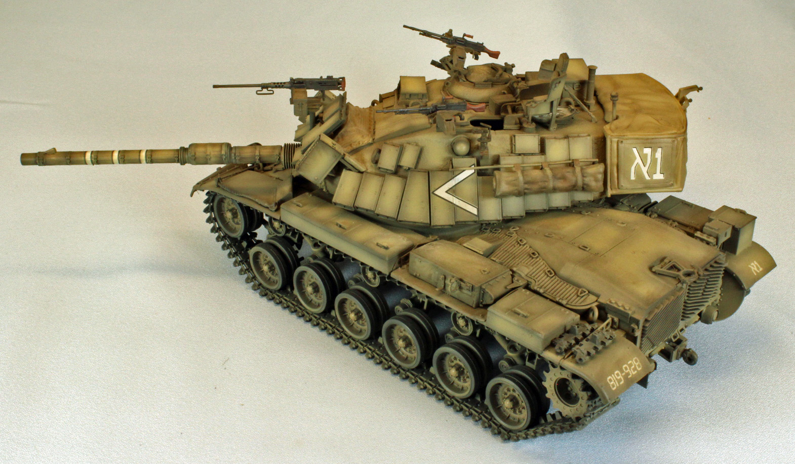
I am more than satisfied with the end result, and all that busy detail looks great on the finished model. The number of small parts, the complicated assemblies and use of photoetch and resin leads me to recommend this kit to experienced modelers only. Go slow, pre-fit everything, and above all, have fun!
I would like to sincerely thank AFV Club for providing this kit for review, and to IPMS USA for giving me the opportunity to review it.