Reviews
Aircraft
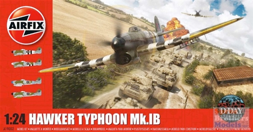
Hawker Typhoon Mk.IB
by Eric Christianson
 Model: Hawker Typhoon Mk.IB Part 1
Reviewed by: Eric Christianson, IPMS # 42218
Scale: 1/24
Company: Hornby Airfix
Price: $149.99
Product/Stock #: A19002
Website: Airfix
Product Web Page: View
Product provided by: Airfix
Part Two of this review can be found here:
http://ipms-seattle.org/reviews/aircraft/2015-EC-Airfix-19002-Part2/
Part Three of this review can be found here:
http://ipms-seattle.org/reviews/aircraft/2015-EC-Airfix-19002-Part3/
Airfix has been producing some of the finest model kits in the industry for 75 years - models that we all grew up with; models that absorbed our allowance money; models with box art that filled our imagination. The company has gone through a lot of changes over the years, but, like our hobby, it’s always been there in the background, beckoning us back to the workbench.
Following their recent trend back into 1/24 scale aircraft kits, Airfix has released the venerable Typhoon Mk.Ib by Hawker Aircraft.
The Typhoon was arguably the RAF's premier ground attack fighter of World War II. Armed with rockets, bombs and Hispano cannon, the ‘Tiffy’ lorded over the Normandy skies, disrupting or completely paralyzing German road traffic and sapping morale, for even the prospect of a rocket attack by the dreaded ‘Jabo’ was unnerving to those on the ground.
This review is the first installment of a three-part series on building and finishing this wonderful kit. Out for some time now, the kit already has several excellent reviews available for it, including several books. That said, there are none that I have found that show how to expose one full side of the engine and cover up the other side, a popular display option that Airfix (curiously) doesn’t offer. Since you cannot attach the engine cowling over the completed engine, exposing specific portions of the engine is not as simple as it might sound. This review will show you how to do this, and what parts you will need to put on and leave off.
Opening the box
The normally dependable US Postal Service did a number on the shipping box containing the kit (see photo entitled 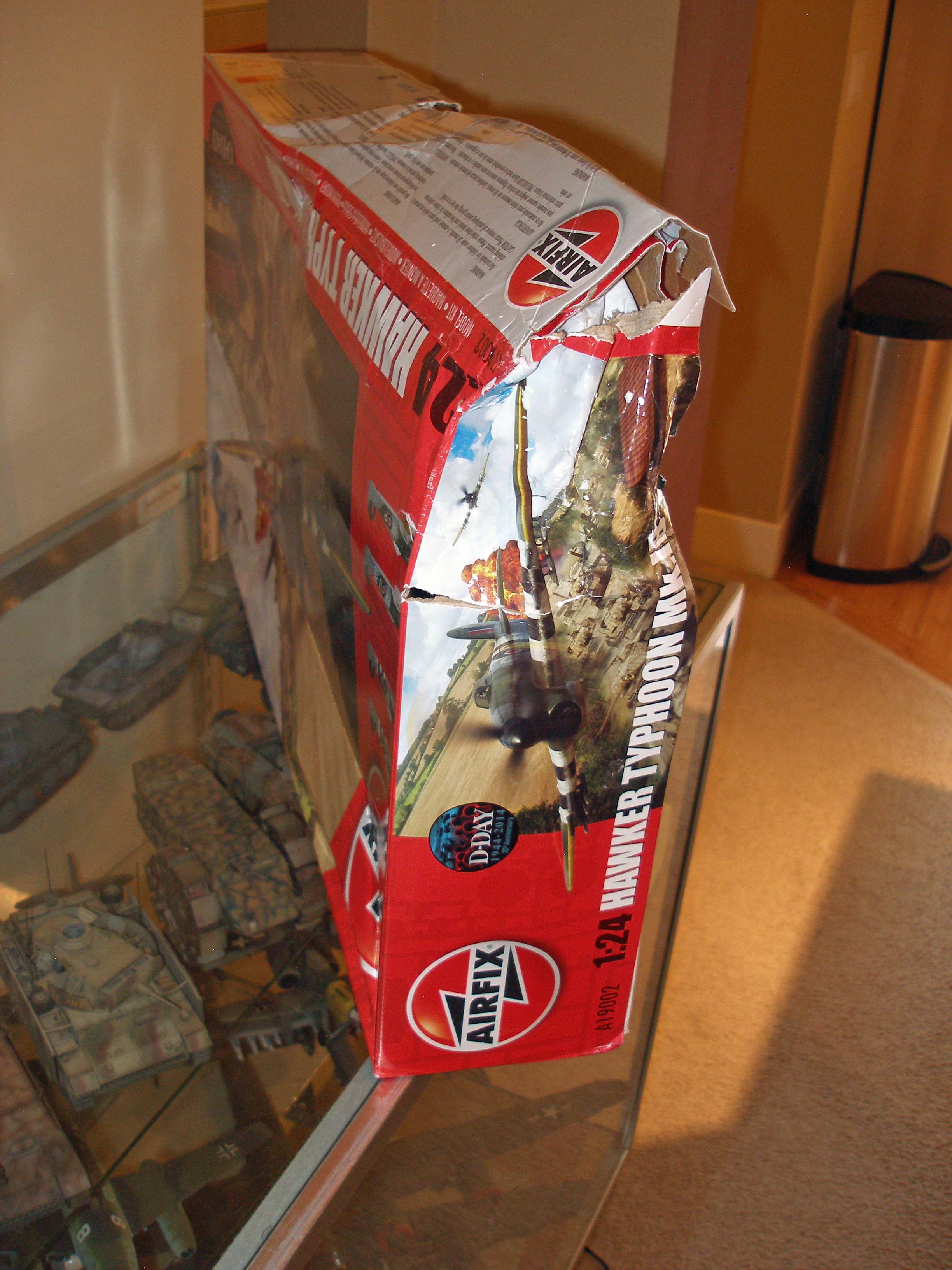 ‘My Tiffy Arrives’), and apologized profusely when it was finally delivered. Examining the contents of the kit, however, produced two conclusions; 1) Airfix did an excellent job bagging and boxing the parts, since the separate bags were able to slide around inside the large box, avoiding damage; and 2) the softness of the plastic used by Airfix, in this particular situation, was key to saving the day. Even the largest parts were able to bend and spring back against what must have been an enormous, yet brief, impact, considering the condition of the outer box. Good Job, Airfix. Not so much, USPS!
Inside I found eight or ten large bags of sprues, an instruction booklet and an enormous single sheet of decals. I didn’t count the sprues as I thought there would be a Parts Map somewhere (there is not). The largest sprue is more than two feet across, the smallest one, perhaps 10 inches.
I must confess – I haven’t built an Airfix kit in years… and was unprepared for the amount of clean-up required, mostly in the form of mold release lines, ejection pin holes, sink holes and such. Just about every one of the 453 parts will require careful attention beyond the normal sprue attachment points. Once cleaned, however, the fit of the parts was excellent. The surfaces of the fuselage and wings have fine raised and recessed panel lines and other detail – a remarkable sight, even in this large scale.
The fuselage comes together in three parts; left and right fuselage halves, and a third large piece along the belly that starts at the rear of the wing root and travels back to the tail section. Likewise, the wings come in five parts; one large lower span with openings for wonderfully-detailed wheels wells, lower port and starboard sections on each side, and two, single top sections with open areas for the gun bays. Three spinners are included, one four-bladed type, and two three-bladed types. One of the three-bladed spinners is shorter and sports a less-pronounced point. Propeller blades are the same for both spinner types. Wheels are delivered in two halves each, and the main gear wheels come ‘pre-flattened’. Wing stores include two types of rockets and rails (8 each), two types of bombs (250lb and 500lb), and what looks like external fuel tanks. Two types of tail planes are included; the initial Typhoon tail, and the later, somewhat larger (Tempest) tail planes. Two sprues of clear plastic are included, and although there seems to be a lot of hubbub on the internet about a flaw on the main canopy (which also exists on mine) I can’t get too worked up about it – the flaw can only be seen from a certain angle and even then, only if you’re looking for it. A big dance around a small fire – in my opinion.
Finally, Airfix chose to go without photo-etch, and I know I wouldn’t be the first in line to congratulate them on this decision. A subject of this size, with PE, would have been a completely different modeling experience, and not nearly as enjoyable - at least not for me.
The kit comes with the following four color and decal schemes represented:
- ‘D-Day Spearhead’, MN666 ‘CG’ Aircraft flown by Wing Commander Charles Green, No. 121 Wing, Royal Air Force Holmsley South, Hampshire, England, and B.5 Le Fresne-Comilly, Lower Normandy, France, June, 1944
- ‘Normandy Workhorse’, DN252 ‘ZY-N’, No247 Squadron, 2nd Tactical Air Force, France and Belgium, June-September, 1944.
- ‘Sharkmouth’, MP197 ‘MR-U’ No.245 Squadron, 2nd Tactical Air Force, Germany and RAF Warmwell, Dorset, England, June-August 1945.
- ‘Canadian Bomber’, RB389 ’18-P’ No.440 Sqn (Royal Canadian Air Force), 2nd Tactical Air Force, Netherlands and Germany, February-May, 1945.
The Instructions
The instructions are printed in a gorgeous, full color, large-format booklet, that with everything else on my workbench, I found a little ungainly. As a consequence, the first thing I did was to cut this beautiful booklet up into separate pages (!!), and organize these into several sections: 1) what I’ve done, 2) what I still need to do, and 3) finish options. Cutting down the somewhat cumbersome booklet allowed me to use single pages on my workbench, as well as separate decal & painting keys for easier access.
One thing Airfix does that few other manufacturers do is to use up sprues in order of assembly. That kind of thing really helps on projects of this size – some of the sprues are three feet wide! That said, there are a few exceptions… don’t spend a lot of time trying to find out where parts A18 and A19 are used – you didn’t miss them – they pop up out of nowhere in Steps 204 and 205! For the most part, however, the approach Airfix took in organizing the parts and instructions really helped me find the next part I needed.
On the down side, I did notice that some of the images are missing detail found in the plastic, making orientation more complex than it needed to be sometimes. Also, the image of the control console used for decal placement is missing some of the dials found in the clear plastic and on the decal sheet - nothing big, but an unusual oversight for such a comprehensive document, as is the lack of a parts map of any sort.
The instructions, however, do contain four color photographs of the painted pilot figure and nine full pages of beautiful color photographs and drawings of the four painting and camouflage options, along with comprehensive decal placement directions.
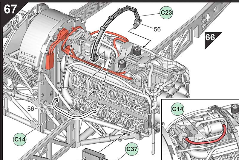
(Note from the Airfix website) Step 67 in the kit instructions omitted the attachment method for the Coffman starter inlet pipe, part C14. This addition to the instructions is displayed below:
Display Options
There are several fundamental decisions that must be made before starting, since parts are used (or not used) as a consequence of using one of several display options. This is because the engine, radiator and gun bay covers are not made to be removable, and will not fit correctly when placed over a completed assemblies. This was a surprise for me, since some of the options I wanted to use were not included in those offered by Airfix.
Display Options - Engine & Radiator
Airfix has provided three display options for the front end encompassing the engine and radiator.
First Option: Completely buttoned up. This option will show the front end of the aircraft as it would look sitting on the ground, ready to fly. All the engine and radiator detail is covered up.
Second Option: Completely exposed. This option will have you (literally) cut off the entire front end of the aircraft’s outer panels, from the cockpit firewall forward, using pre-cut guides on the inside of the cowl parts. This option will display all of the considerable detail found in the front end as if the aircraft was sitting in a hangar undergoing major maintenance.
Third Option: A modified version of the option above, covering the radiator and the lower portion of the engine on both sides, and exposing the engine from the exhaust pipes upward, on both sides and over the top.
It seemed to me, then, that the only way Airfix wants me to preserve those nice lines of the Typhoon superstructure is by completely covering up that beautiful engine. Hmmm…
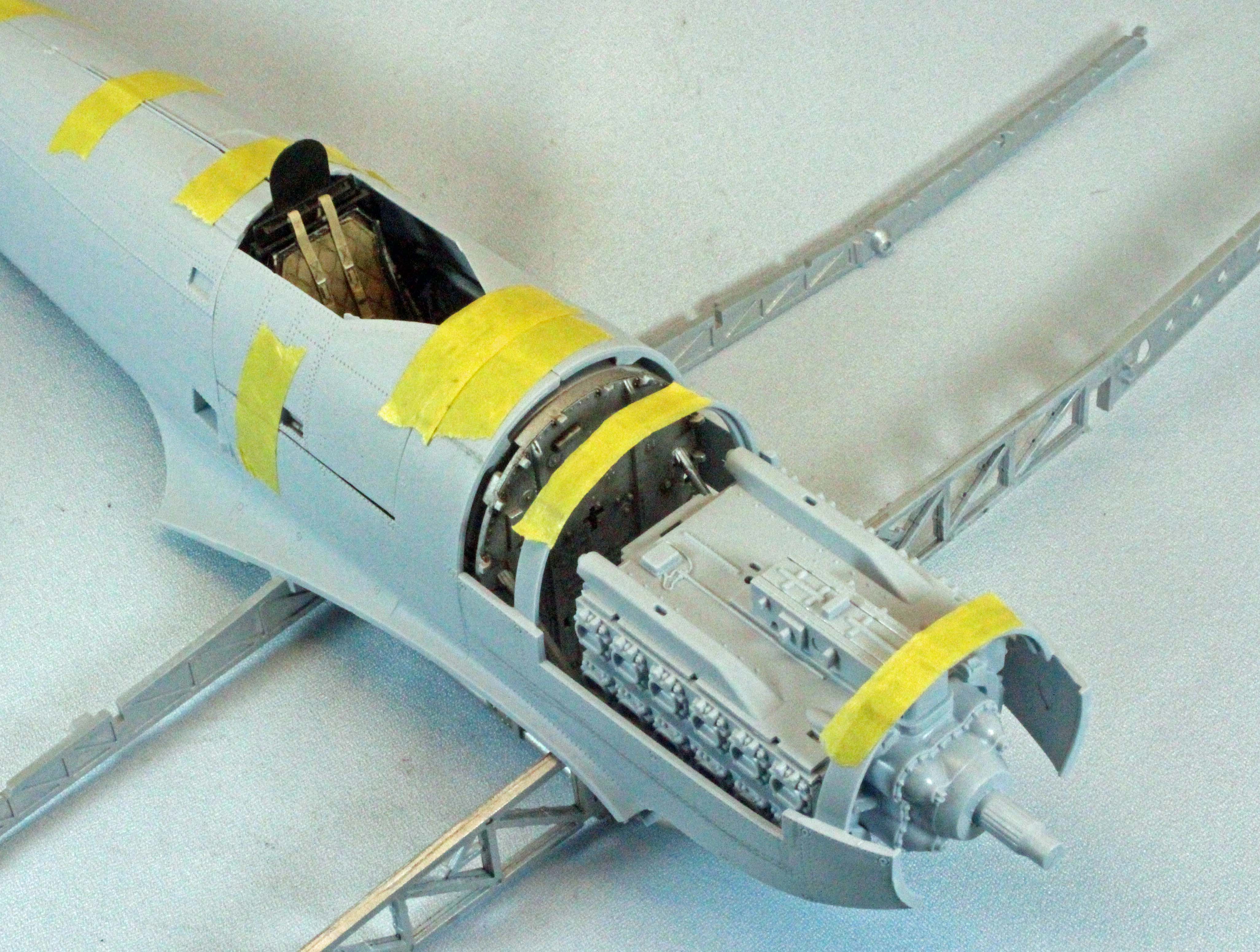
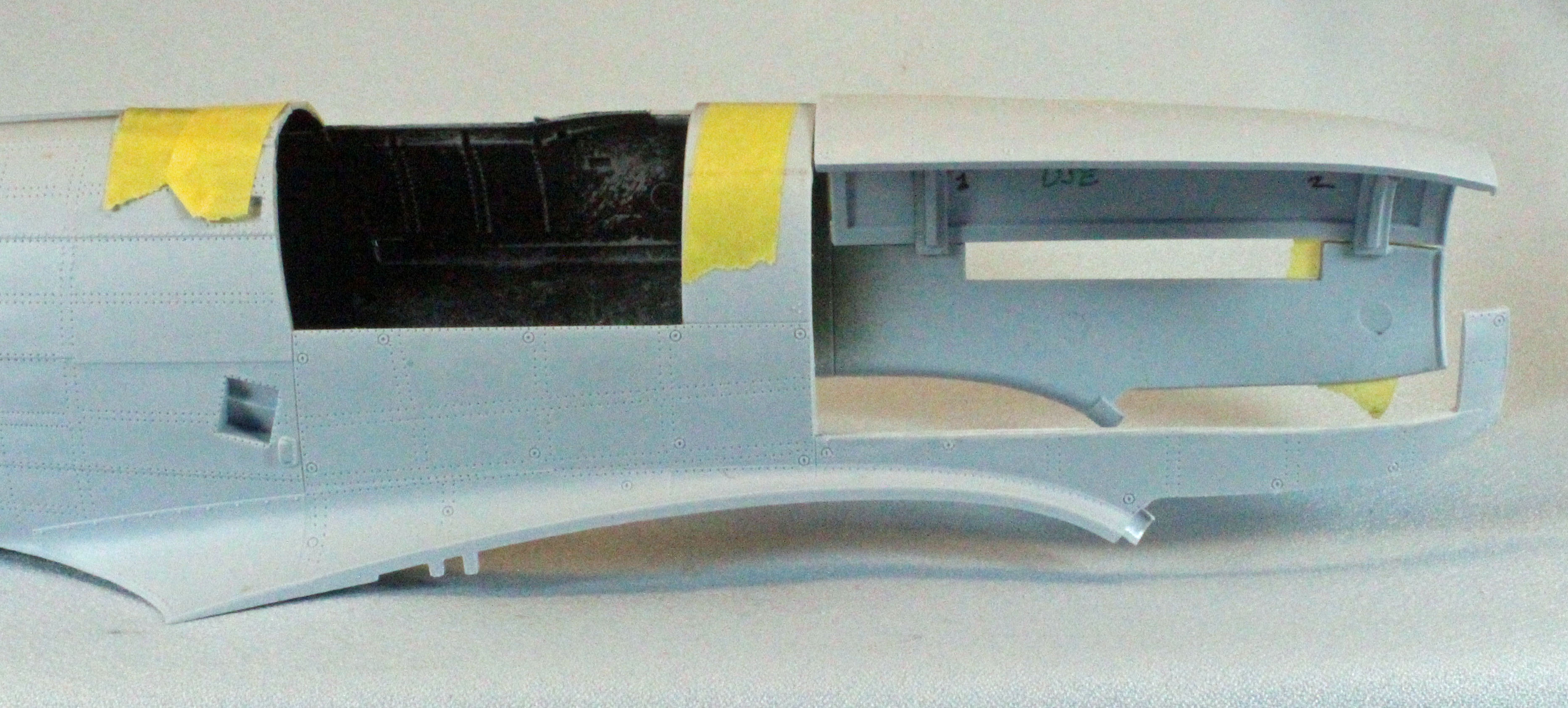
After much review of the instructions and the plastic, I chose to use a Fourth Option – the one not offered. I wanted to cover up the port side of the Typhoon, showing off the long, masculine front of the aircraft, while opening up the starboard side showing off that beautiful engine all the way down to the radiator intake. This would require some minor surgery and a lot of circumvention of the manufacturer’s intentions, but I felt it would produce what I was looking for in such an interesting subject and kit. Rest assured, the Airfix instructions are easy to follow and will show you how to proceed with Options 1-3, but the content of this review will also include the steps I took building the one option not offered.
Display Options - Wing Cannon Bays and Wheel Wells
These decisions are easier. Airfix allows you to show one or both wing cannon bays open or closed, and to show the Typhoon with wheels retracted or lowered (Airfix offers an after-market stand – it is not included in the kit). Sticking to my theme using ‘Option 4’, above, I went with exposing the starboard wing cannon bay and covering up the port side bay, as well as showing the landing gear lowered. The excellent wheel-well detail alone easily drove this last decision.
Airfix conveniently color codes the part numbers (white, green and blue) for all of their display options and includes the following statements in the instructions:
“Part numbers indicated (in Green) should only be fitted to the model if the engine and gun bay details are to be left visible and left uncovered.”
“Part numbers indicated (in Blue) should only be fitted to the model if the undercarriage is to be fitted in the extended position.”
I found that most of these parts, however, can be used and do actually fit under the cowls and/or wing panels. The color codes simply mean that the parts are not required and will be covered up. Opening up the aircraft in the manner that I plan to, however, will require that some of these parts be used, and I have identified these in the appropriate section, below. I built the full engine and radiator, took some photos for this review, and then snipped out the few parts that kept the engine cowls from seating correctly – these are identified in the appropriate section below as well.
I wanted my Typhoon dressed in full invasion stripes so I am using scheme one (‘D-Day Spearhead’), although I’ll be going with different unit markings.
The Build
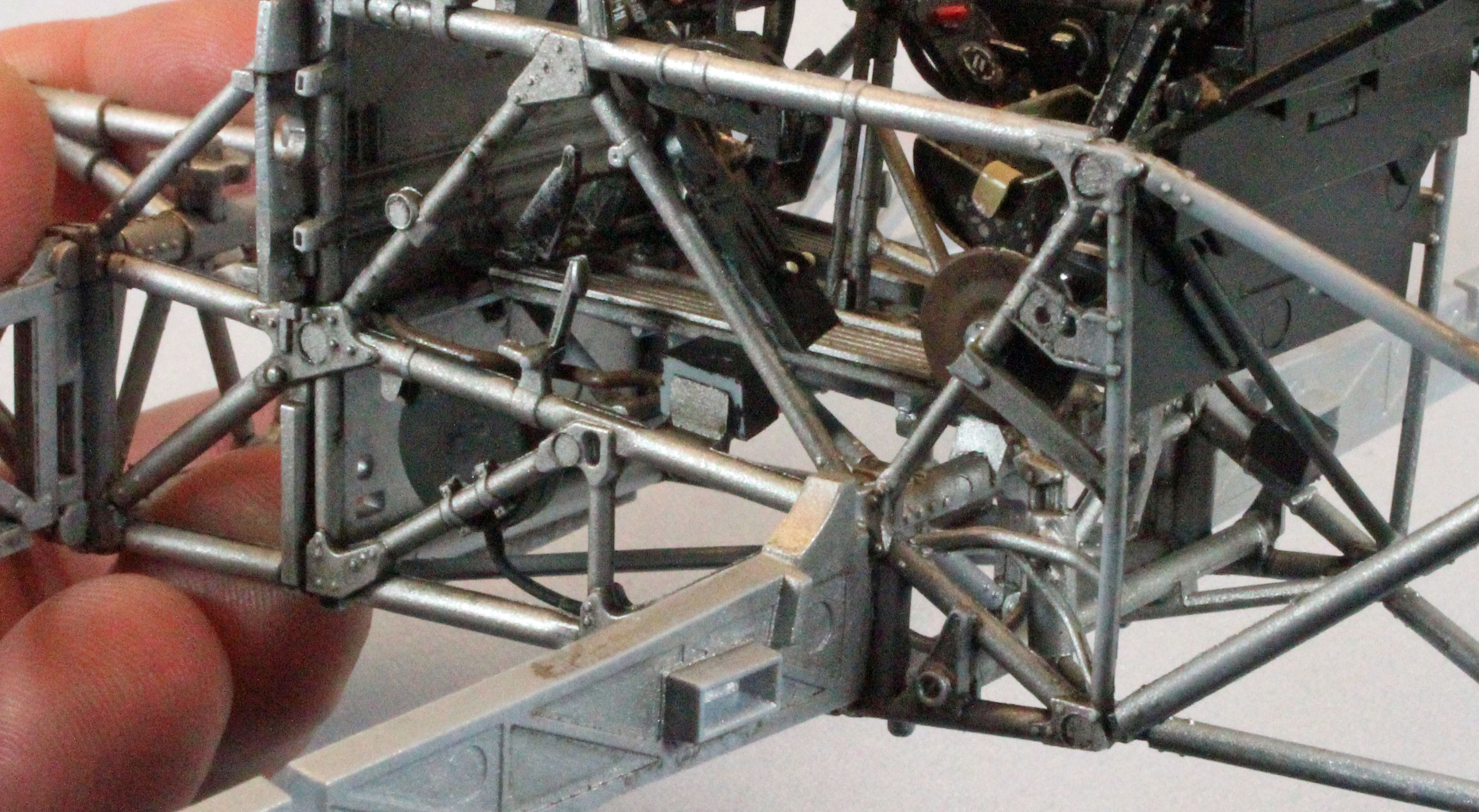
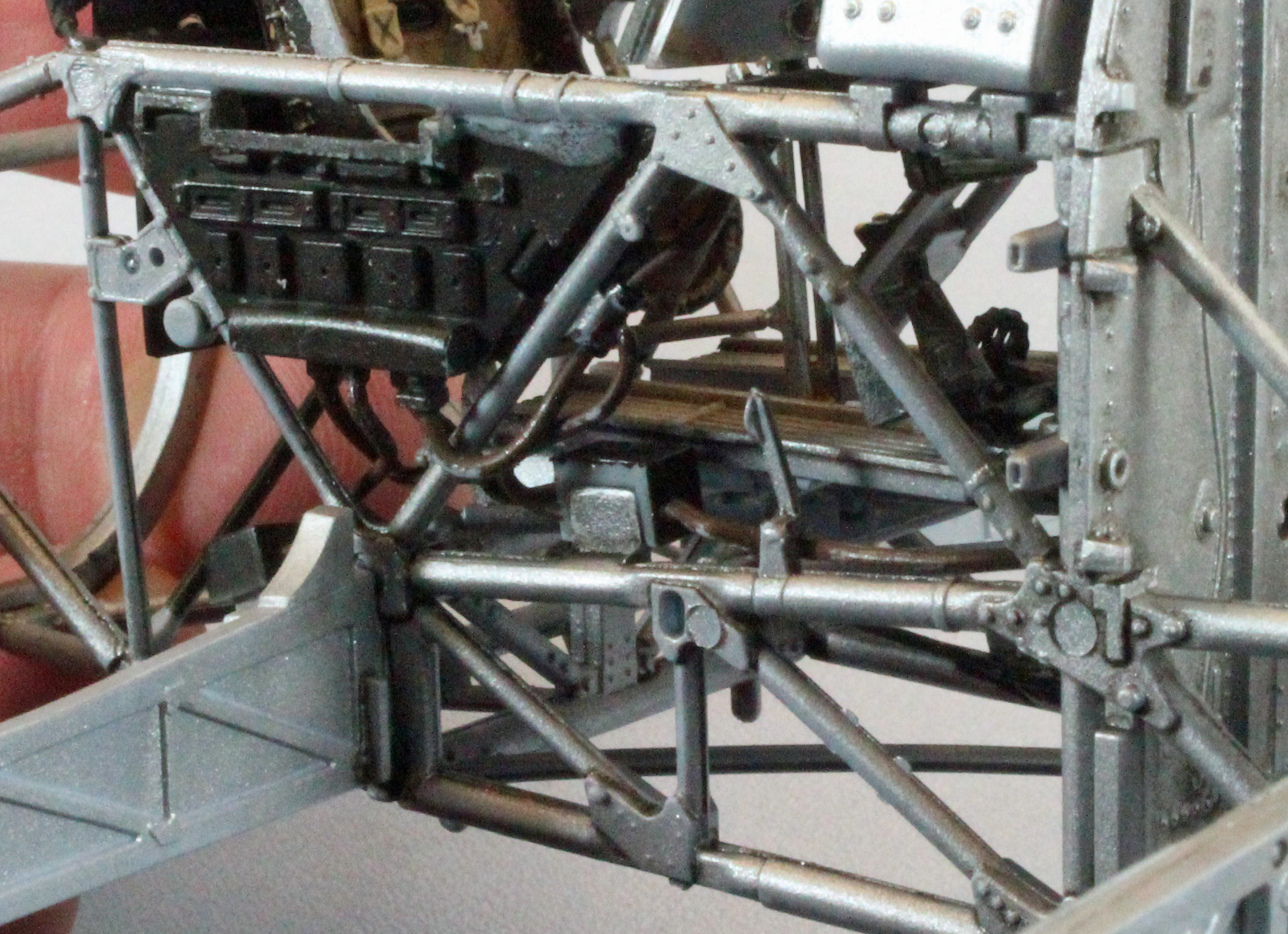
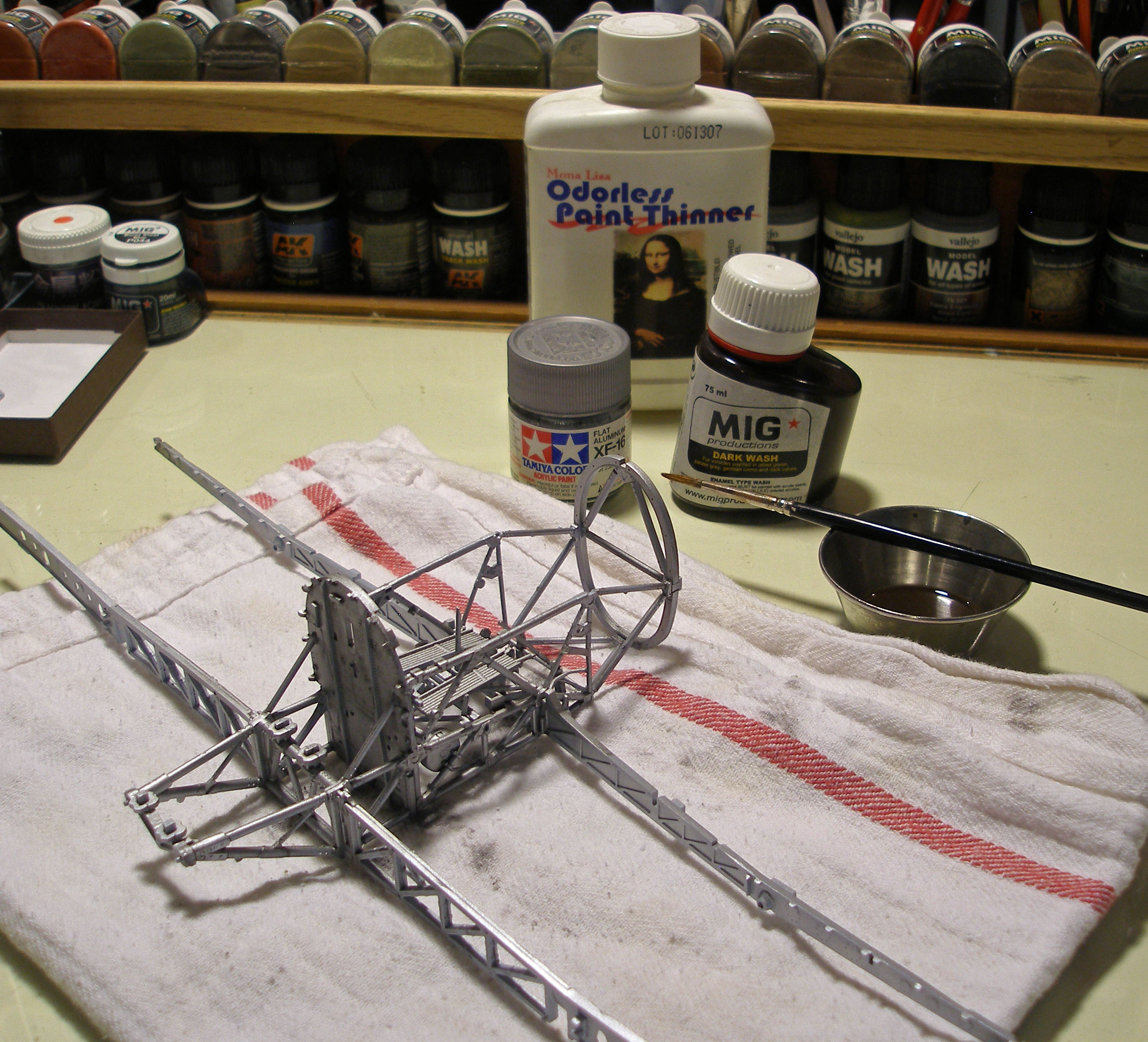
Internal Framework in the front end
Everything starts with the complex-looking - but surprisingly simple - framework that makes up the front-end and main wing spars. It’s a good idea to get familiar with this assembly because you will become close friends with it in the next 90 or so steps to come. Even though I was very, very careful to get everything perfect in these first few steps, I continued to have some fit problems later, so a word of warning: don’t rush. Part 56 in Step 4 was a poor fit, and I am pretty sure things were cleaned and lined up right. I skipped Step 6, as the parts here are (green) colored-coded and I was going to cover up the oil-cooler/air intake. After completing Steps 1 – 8, I stopped to paint everything Tamiya XF-16 Flat Aluminum, following by Mig Dark Wash and Mig Brown Wash oil washes. At this point it’s hard to know what will be visible in the end so everything gets painted and weathered.
Parts Not Used for ‘Option 4’:
Step 6 Parts A25, B19, B20.
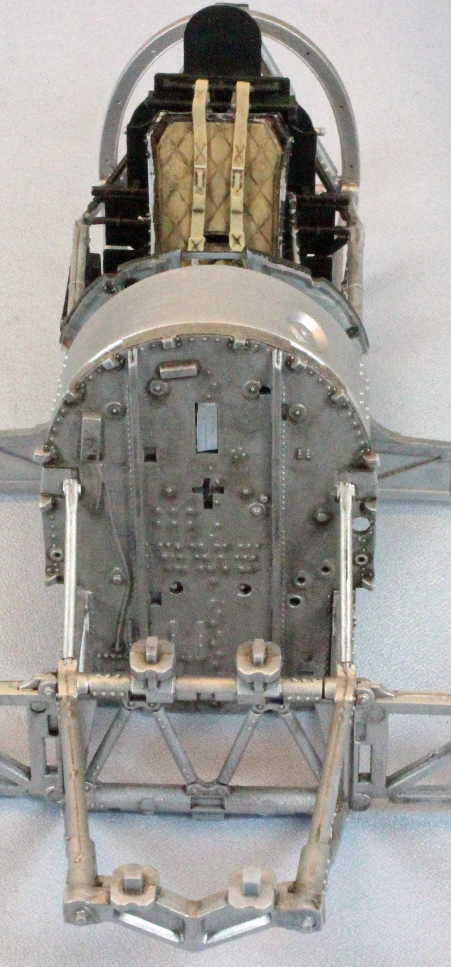
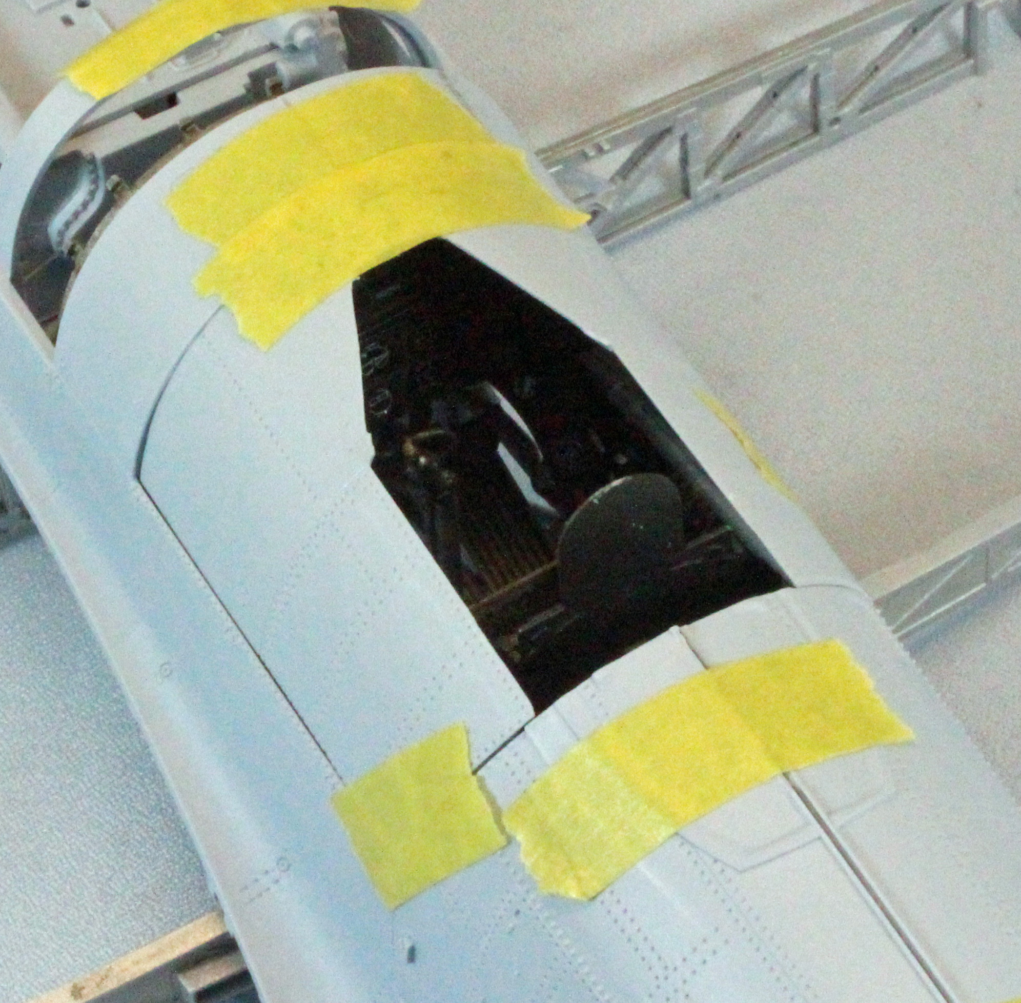
The Cockpit
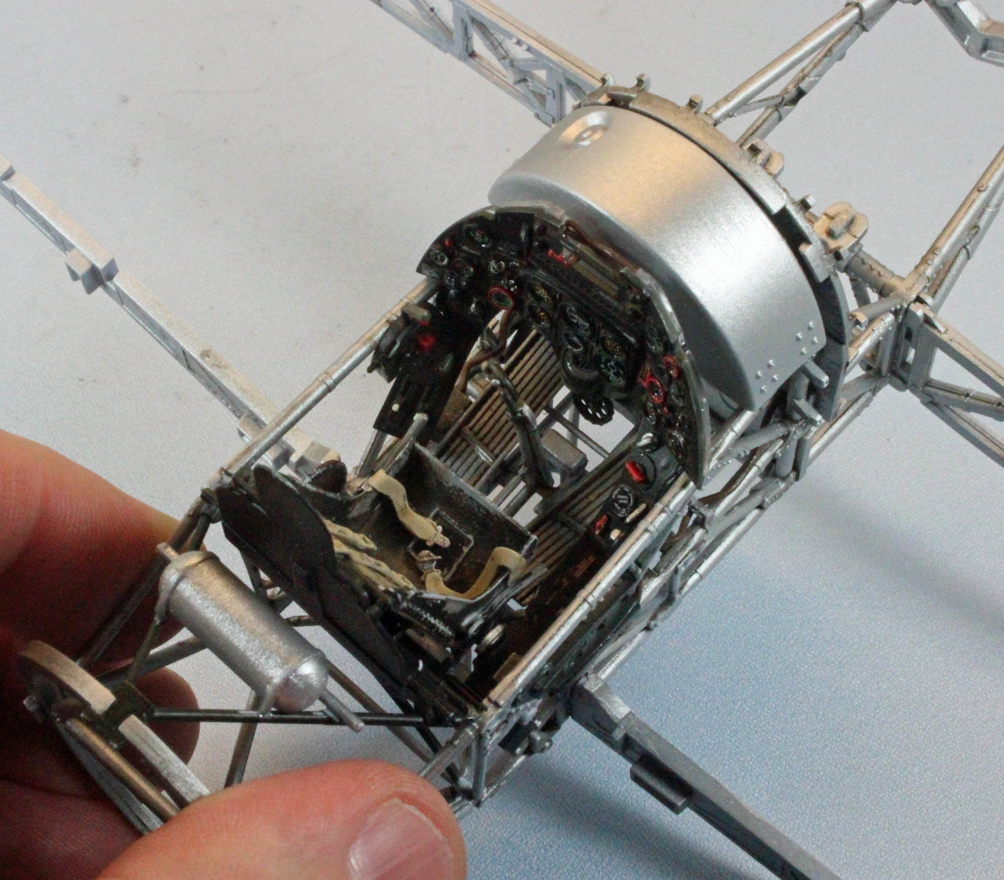
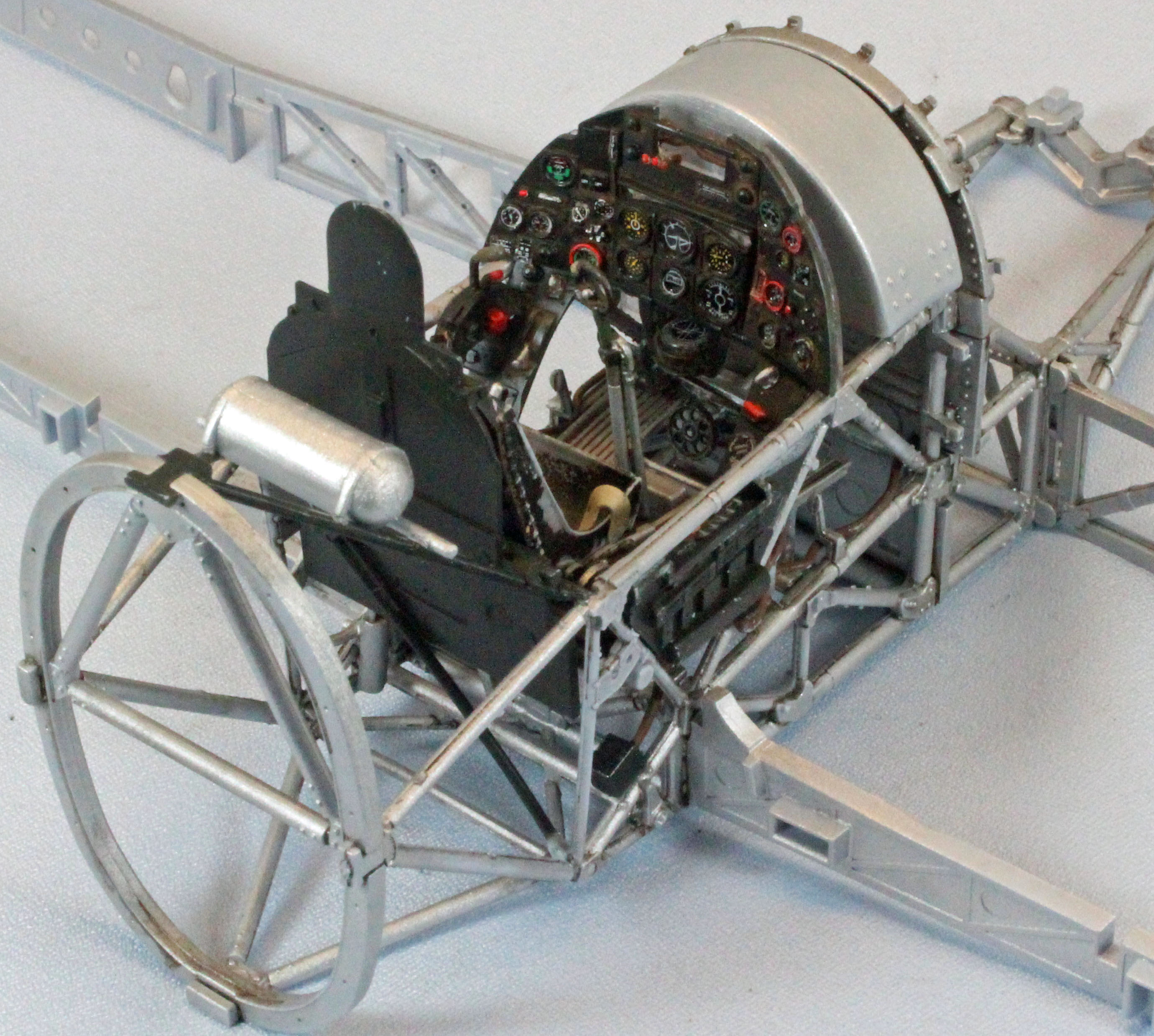
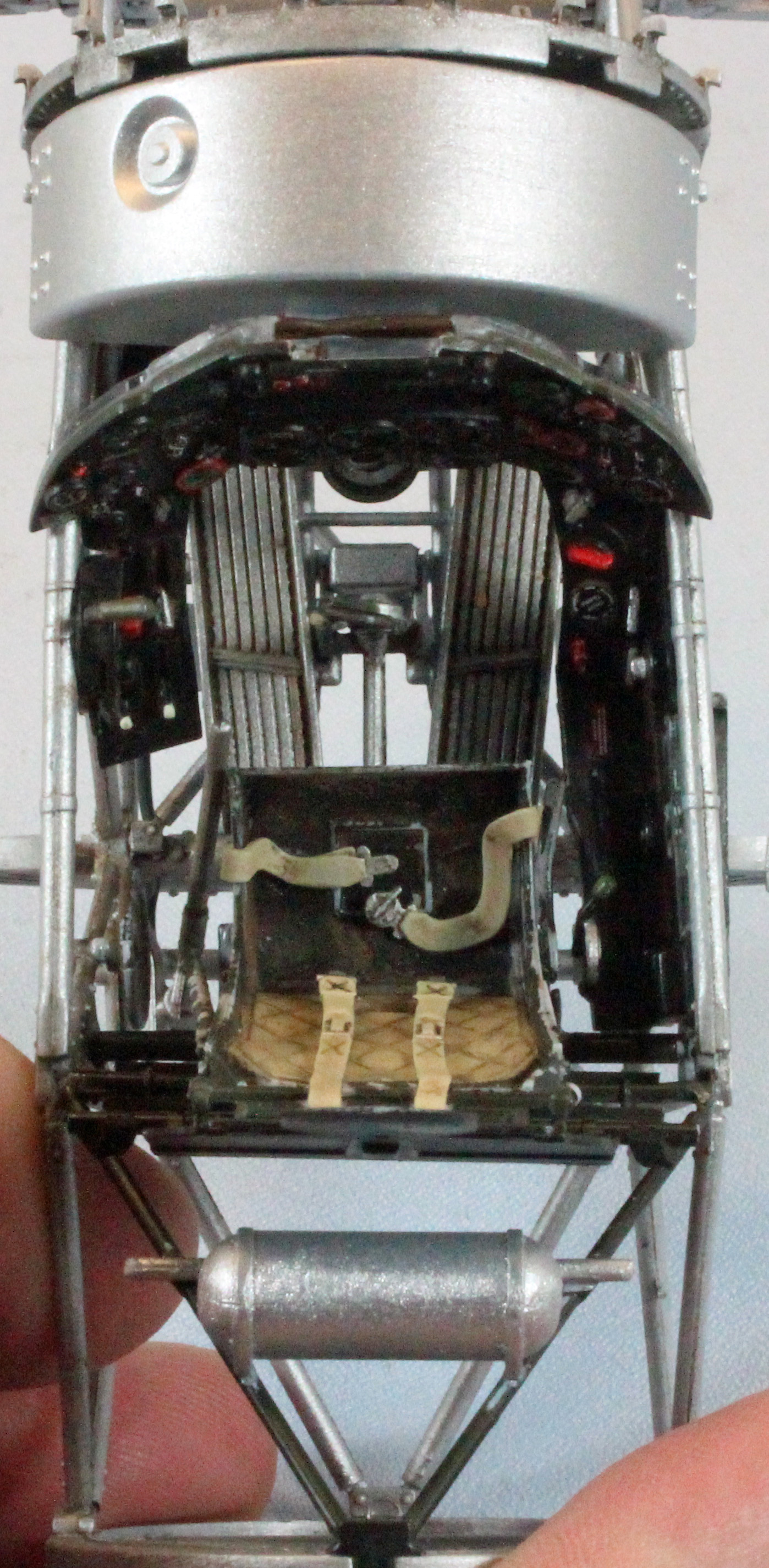
Arguably the most challenging - and certainly the most time consuming - part of the build, the Typhoon cockpit is a wonder in miniature…and somewhat frustrating, since most of what you create will be hidden within the relatively small opening in the top of the fuselage. Still, in this scale, time spent on the cockpit matters.
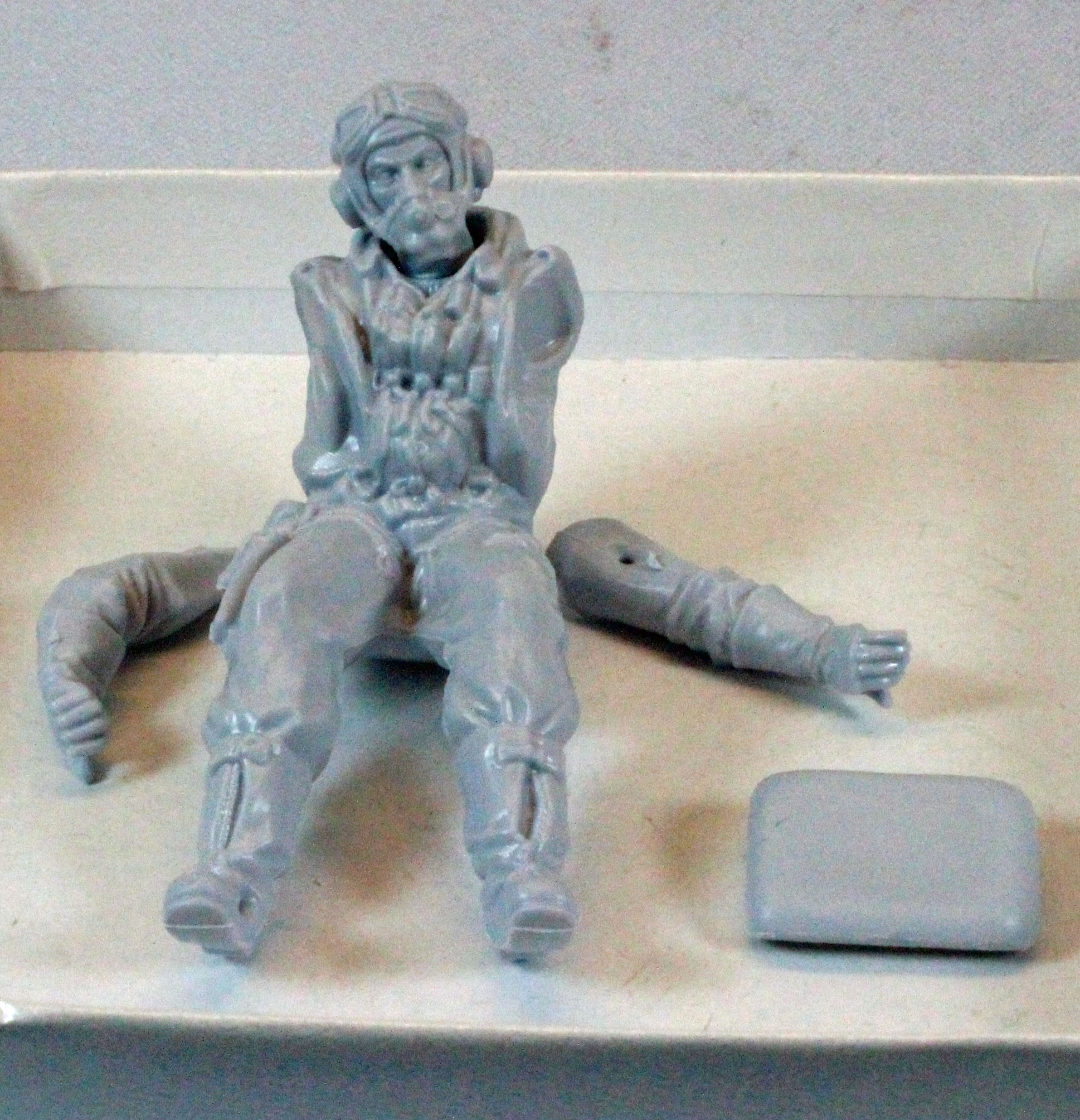
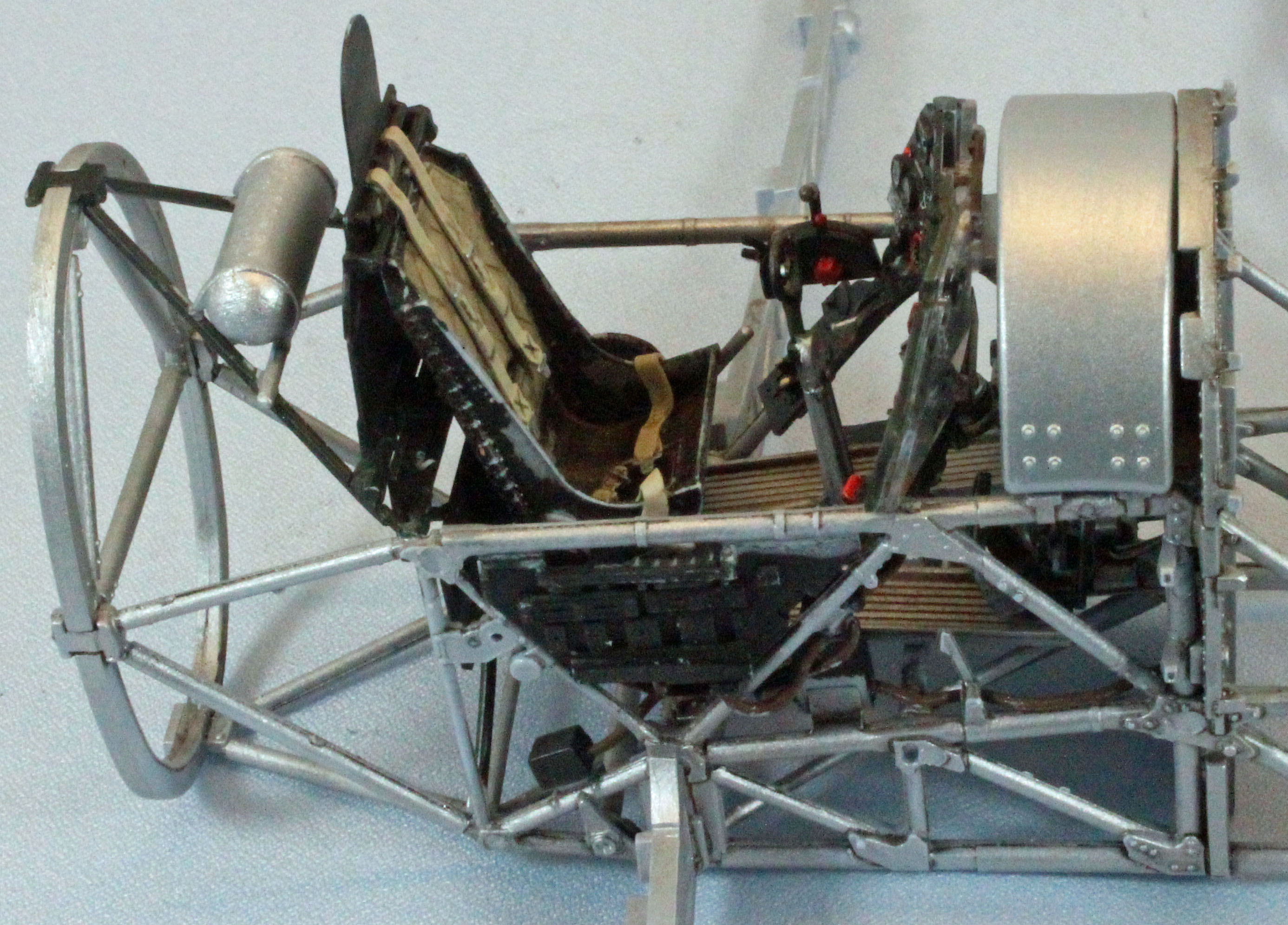
Encompassing 29 steps starting with Step 9, most of the finish will involve just a few colors and washes, with the decals and stenciling taking up the majority of the effort. I finished most of the non-metallic parts in off-black per the instructions, but other reviews have many of these parts in interior green. I left the reasonably detailed figure and parachute out so I could expose the seat and seatbelts.
I began with snipping off and cleaning all the parts identified in Steps 9-38 and assembled, painted and weathered the five or six subassemblies therein before going back to the framework and instructions. While the seat and seatbelts were molded with a nice cross-hatch pattern, I would have liked it to be a little more pronounced – the pattern was so shallow it was difficult to apply a wash to it – I had to actually paint the hatch pattern on by hand. On the other hand, the choice of providing molded plastic seatbelts vs over-engineered photo-etch versions, in my opinion, was brilliant. Thank you, Airfix.
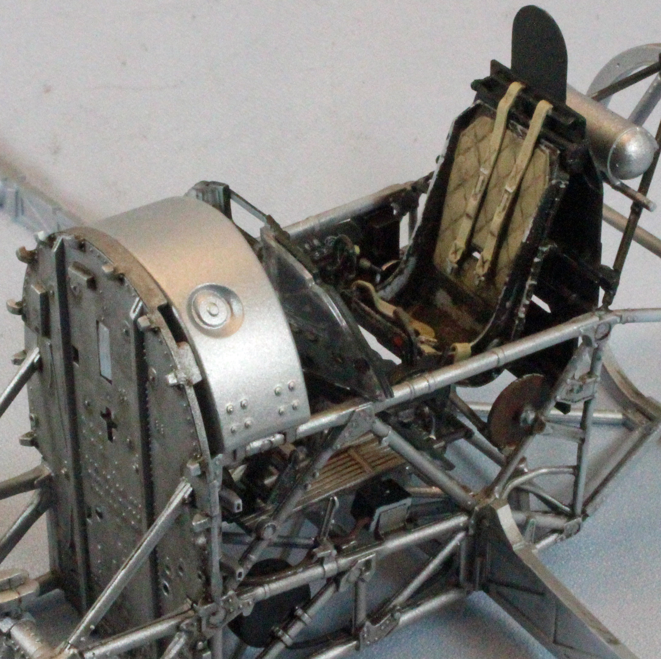
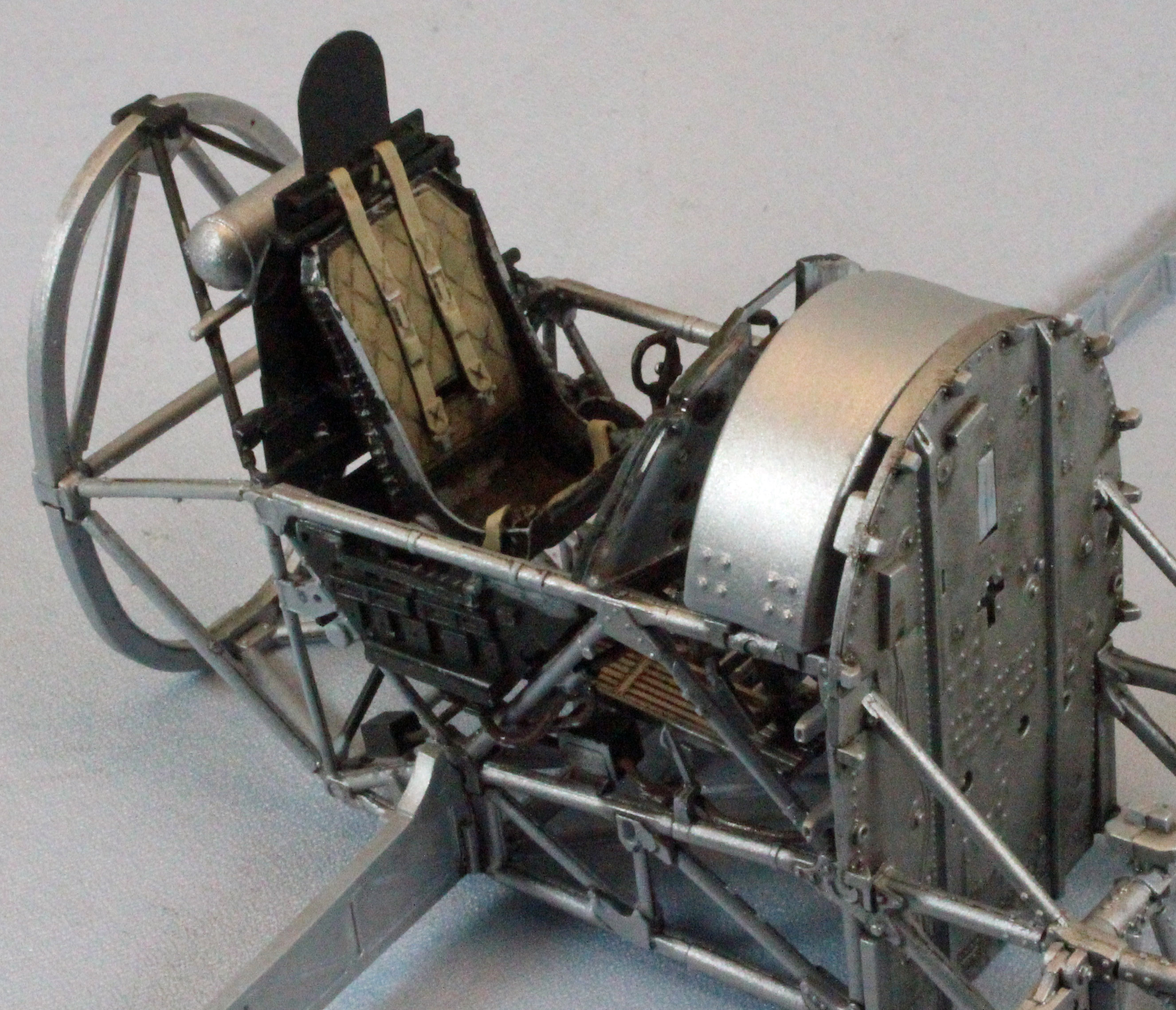
Construction generally followed what Airfix had in mind, with one exception: I installed the pilot’s seat in Step 20 instead of Step 16. After trimming the connection points, the seat snuggled nicely into its place with the proper angle to accept the two shoulder harnesses since, in this later step, the seat had the rear armor plate to lean against.
I had to pry parts B14 and B18 apart in Step 23/24 and remove the guide pins before re-attach them to get them to line up right. This was not an uncommon task, throughout the build.
Curiously, the oxygen bottle (Parts A04 and B15 in Step 32) is marked in green, meaning this should be left out if you choose to close up the fuselage – but the bottle is nowhere near the engine compartment so I’m not sure what that’s about.
I painted the cockpit framework Tamiya XF-16 Flat Aluminum and applied Mig Dark Wash and Mig Brown Wash oil washes to it. For the pilot’s seat I used Tamiya XF-16 Flat Aluminum, shot it with hairspray, and then covered that with Tamiya XF-69 NATO Black, before rubbing off some of the black paint with a stiff brush and a little water to expose the metallic finish underneath. I used Vallejo Model Air 71.028 Sand Yellow for the seat cushion, Vallejo Model Air 71.075 Sand Ivory for the belts, and then applied Mig Dark Wash and Mig Brown Wash oil washes to both.
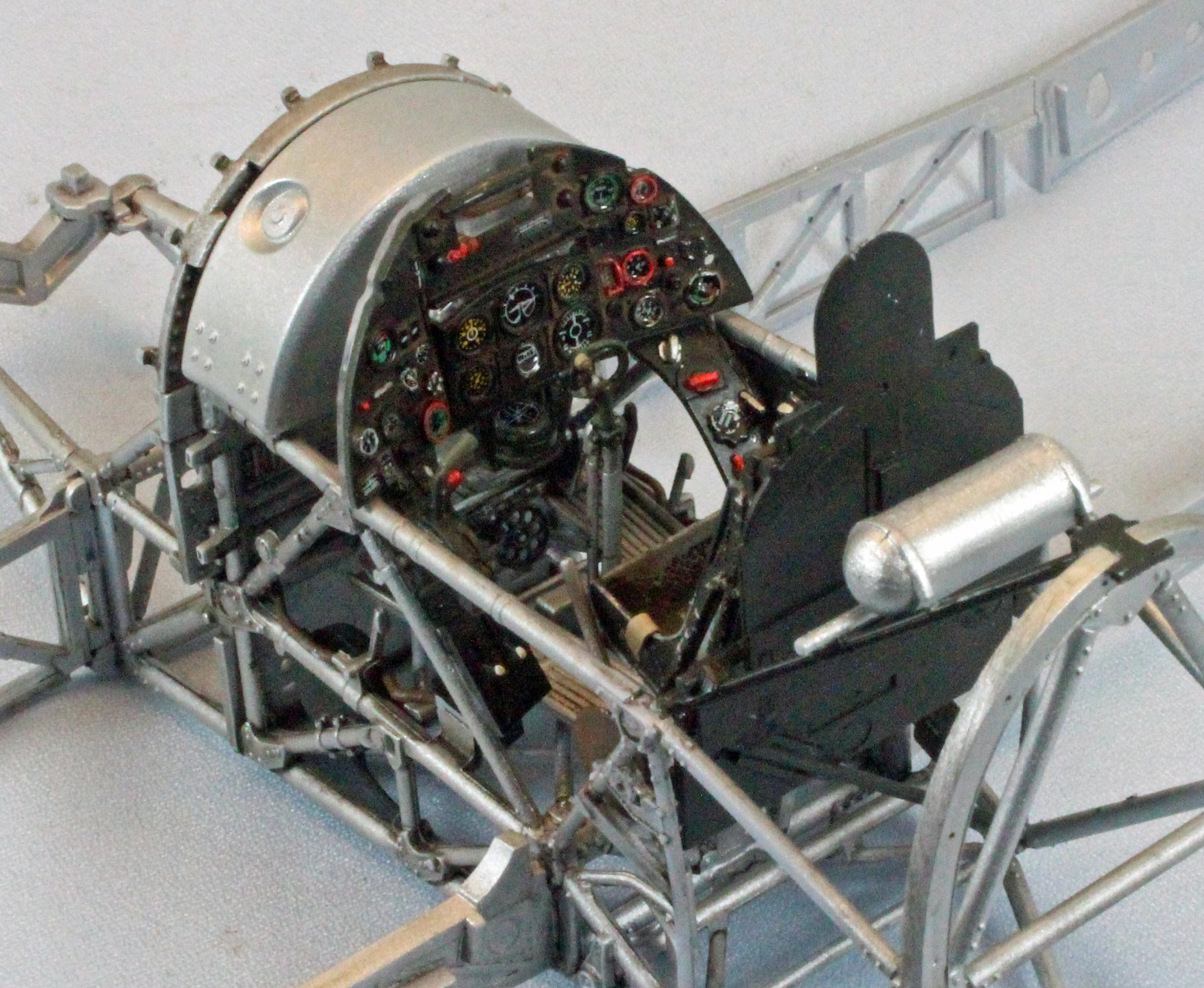
The instrument panel and side consoles were painted Tamiya XF-69 NATO Black, and detailed with Tamiya X-11 Chrome Silver, Vallejo Model Air 71.085 Ferrari Red over Model Air 71.001 White, and washed with Mig Brown Wash oil wash. I used Vallejo Panzer Aces 312 Leather Belt for the trim wheel and all cables, Tamiya XF-69 NATO Black for the black boxes and compass structure, after dabbing some liquid mask on the compass face itself.
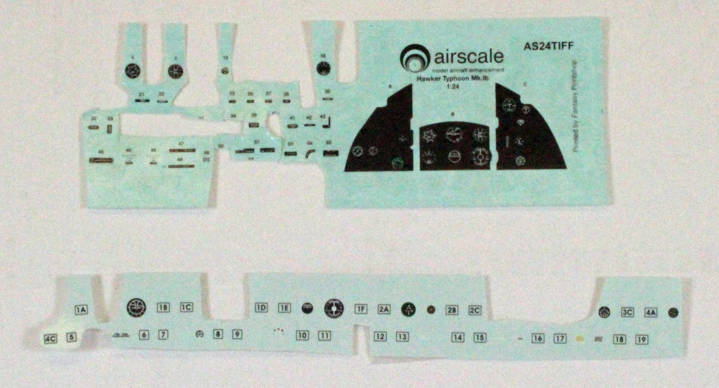
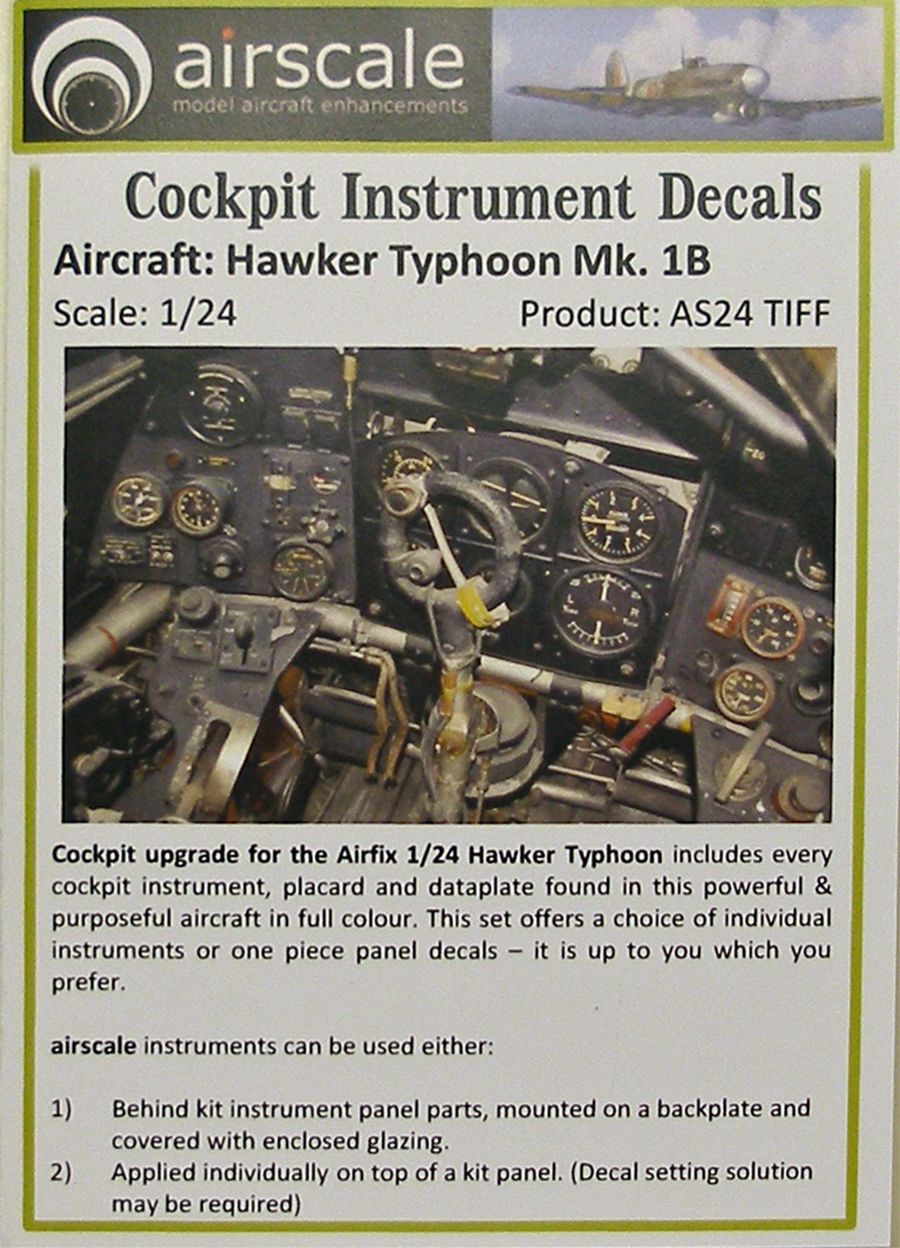
Decals and placards:
These were a mixture of the Airfix kit decals and an after-market set from Airscale put together specifically for this kit when it first went on sale. The Airscale set is no longer offered, but a generic 1/24th scale RAF set by them can be found here: (Airscale Website - 1/24 RAF Cockpit Decals ). A separate review of the set I used with this build, can be found here: (IPMS Review of Airscale Typhoon Cockpit Decals).
Once everything was dry, but before attaching the subassemblies and instrument panel, I sprayed a light coat of Vallejo Matt Varnish over all the exposed surfaces, followed by drops of Future on all the dials.
With the subassemblies and instrument panel completed, I attached everything per the order specified by Airfix without any significant issues. Installing the right-hand console in Step 24 is easy once you realize that one of the cables underneath the panel passes outside the cage – the illustration in next Step (25) shows this clearly. The three small boxes with cables coming out of them (Parts A10, A12, and B11) fit into their various positions perfectly. Apparently, unlike some manufacturers, someone at Airfix actually built this kit, and they got it right.
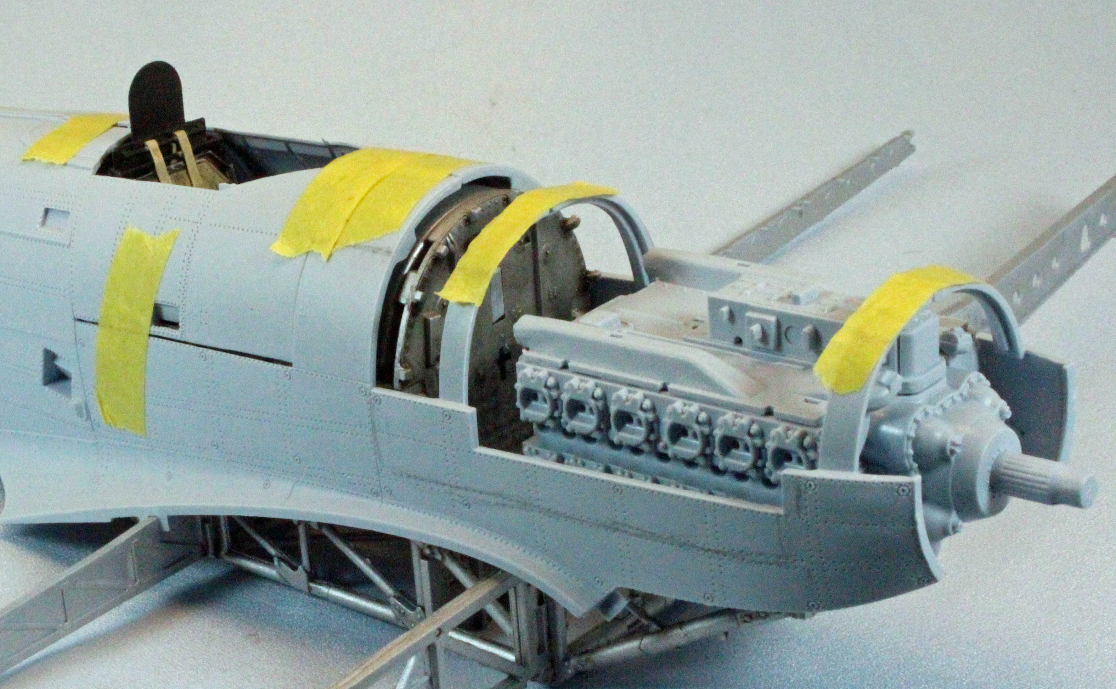
The Engine
Similar to the assembly sequence used with the cockpit, I cleaned all the engine parts (Steps 39-74) first and then went as far as I could before stopping to paint. I sprayed the engine block Tamiya XF-69 NATO Black after Step 48, save for the three parts in Step 46, which were painted Tamiya XF-16 Flat Aluminum and then attached underneath. I painted the various parts marked with (Humbrol 56 Aluminum) in the instructions using Tamiya XF-16 Flat Aluminum, and the parts in Step 51, 55 and 56 with Alclad Pale Burnt Metal over Alclad Black Primer & Microfiller. I hand painted the parts in Steps 57, 58 and 63 a mixture of NATO Black and Flat Aluminum. When everything was dry I had a ball putting everything together! With very few exceptions, the fit of all the parts was superb, including the long and snaky piping that seemed to hug the engine block and framing perfectly. In Step 53 I had to shorten the curly end of Part C19 by just a bit, and drill a small hole in the appropriate place on the engine block to receive it.
Before weathering, I took some pictures and then went about cutting and chopping the following parts off to fit under the cowling parts:
Parts Removed to fit the top and port engine cowls
Step 38 – Part C21
Step 55 – Part C06
Step 57 – Part C09, C47
Step 61 – Part C35, C39
Step 67 – Part C23 – Only snip off the half that is covered up…
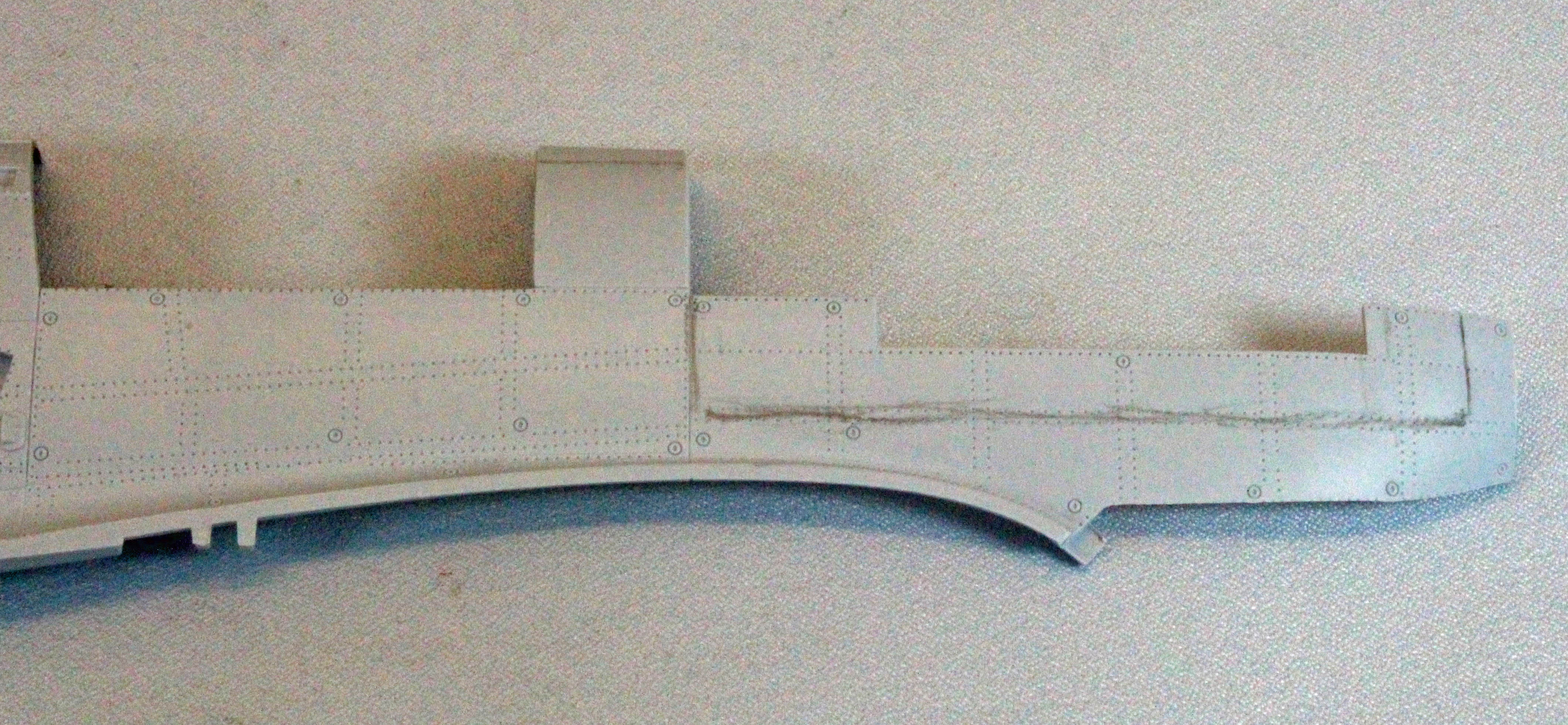
I knew I was going to cut away a section of the starboard side-cowling, and now that the engine was complete, I had an idea of what I wanted to expose. I drew a line on the plastic with a pencil (see images labeled ‘Cutout-Before & Cutout-After’) and cut the piece away to expose as much as possible.
The Radiator and Lower Front End
I chose to cover the bottom of the front end up. The detail is nice, but I felt the several large pieces found there didn’t inspire the same ‘wow’ factor as the engine and cockpit. The fit of the two halves (Parts D09 and D10) in Step 76 was poor and took some filling and sanding to smooth up. I made sure to paint Part D15 in Step 75 Gunze Mr. Color C363 Medium Sea Grey before attaching it… the first (external) paint color used so far – progress!
I assembled all the parts in Step 80 and Part D17 in Step 86 before painting them Tamiya XF-16 Flat Aluminum, and while I had the airbrush going I painted the rest of the odds and ends the same color per the instructions.
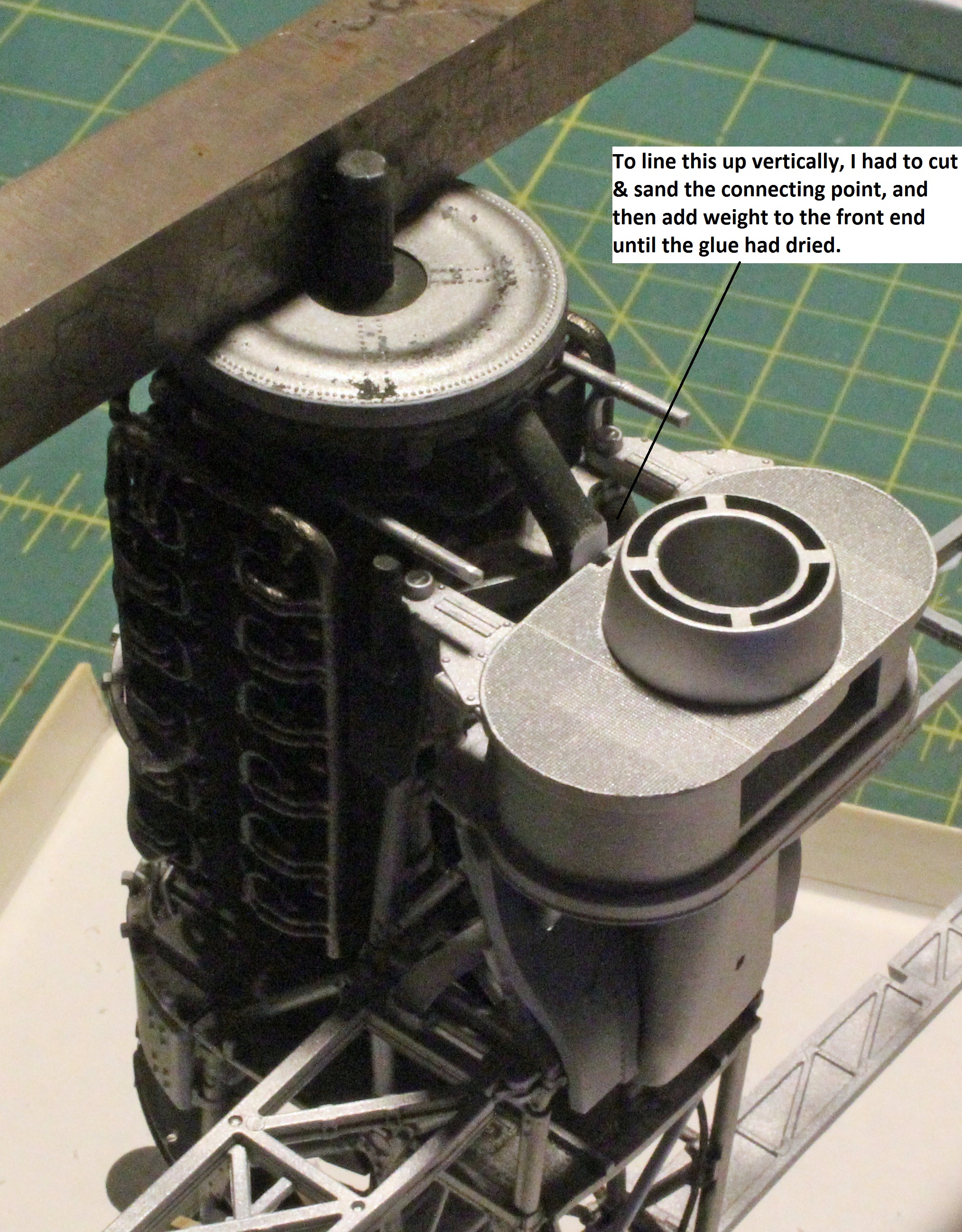
The instructions contain a scary-looking set of images in Step 81 that show angles and measurements in millimeters, making one think that things are pretty crucial here, but, once you start putting the big pieces where they go you will find that there is precious little movement or play in any of the parts to adjust one way or the other. All you are able to do is put the glue on and cross your fingers that it’s right! The only problem I encountered was attaching the assembly from Step 85. In place, it wanted to push the air-cooler out just a bit, producing an angle that wasn’t 90 degrees. I ended up snipping off the point where it connects to the air cooler and adding weight while the glue dried – see the image labeled ‘Step 85’. I hoped this wasn’t a harbinger of things to come – all I could do is trust my instincts and wait.
Once the entire engine and radiator sections were assembled, I gave everything two coats of Mig Brown Wash and let that dry. I then used Mig Dark Wash straight from the bottle on many of the aluminum parts to knock them down a bit. Finally I used a Quilters (Silver) Pencil and highlighted various areas that were painted NATO black.
I then sat back to look at my creation. The jowly front-end of this big guy was starting to look like a Typhoon!
Parts Not Used for ‘Option 4’:
Step 68 – Parts D24, D26
Step 70 – Part D01
Step 71 – Part D25
Step 72 – Part D02
Step 73 – Parts D18, D19
Step 80 – Part D12
Step 82 – Parts D07, D08, D11
Step 83 – Part D03
Step 84 – Part D04
Step 87 – Part C17
Step 159 – Part N03
Conclusion
When I started this project, I was a little intimidated. I had not built an Airfix kit in a long time; and precious few aircraft kits in the last few years for that matter, focusing mainly on armor. Those that I did build, however, were complex projects and I enjoyed them, so I knew I would be able to build this kit. Now that I’ve finished the cockpit and engine, I find myself really excited about the remainder of the build coming up. This, to me, is a clear personal indicator that Airfix has a real winner in the big scale Hawker Typhoon 1b. The fit is wonderful (which always helps), but other decisions peculiar to Airfix also make it a lot of fun to build: molded plastic (yet separate) seat belts, no photo-etch, sprues that are used up in a rational order, crazy piping that at first looks like a headache, and then simply slips through holes and clicks into place like a dream – all of these things help to create a thoroughly enjoyable modeling experience.
I recommend this kit to all modelers who are up to the small challenges that a kit with so many parts and options will offer. I suggest that you make your big decisions up front, spend the time to carefully clean the parts thoroughly once separated from the sprues, and dry-fit everything. Airfix has put a lot of effort into making sure the parts fit, and if they don’t, there is a good chance that you’ve got something wrong. Slow down, use your references, and enjoy the ride!
First segment (this one): Internal fuselage and wing structure, cockpit, engine and front end.
Second segment: Wing, gun bays, wheel wells, fuselage and tail.
Last Segment: Weapon stores, final assembly and finish.
I would like to thank Hornby Airfix for providing this kit for review, and to IPMS USA for giving me the opportunity to review it.
.jpg)
.jpg)
.jpg)
.jpg)
.jpg)
.jpg)
.jpg)
.jpg)
.jpg)
.jpg)