Reviews
Armor
Meng T-90A wTBS-86 Tank Dozer
by Eric Christianson
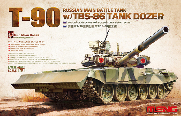 Model: Meng T-90A wTBS-86 Tank Dozer
Reviewed by: Eric Christianson, IPMS # 42218
Scale: 1/35
Company: Meng Models
Price: $59.95
Product/Stock #: TS-014
Website: Meng Models
Product Web Page: View
Product provided by: Squadron
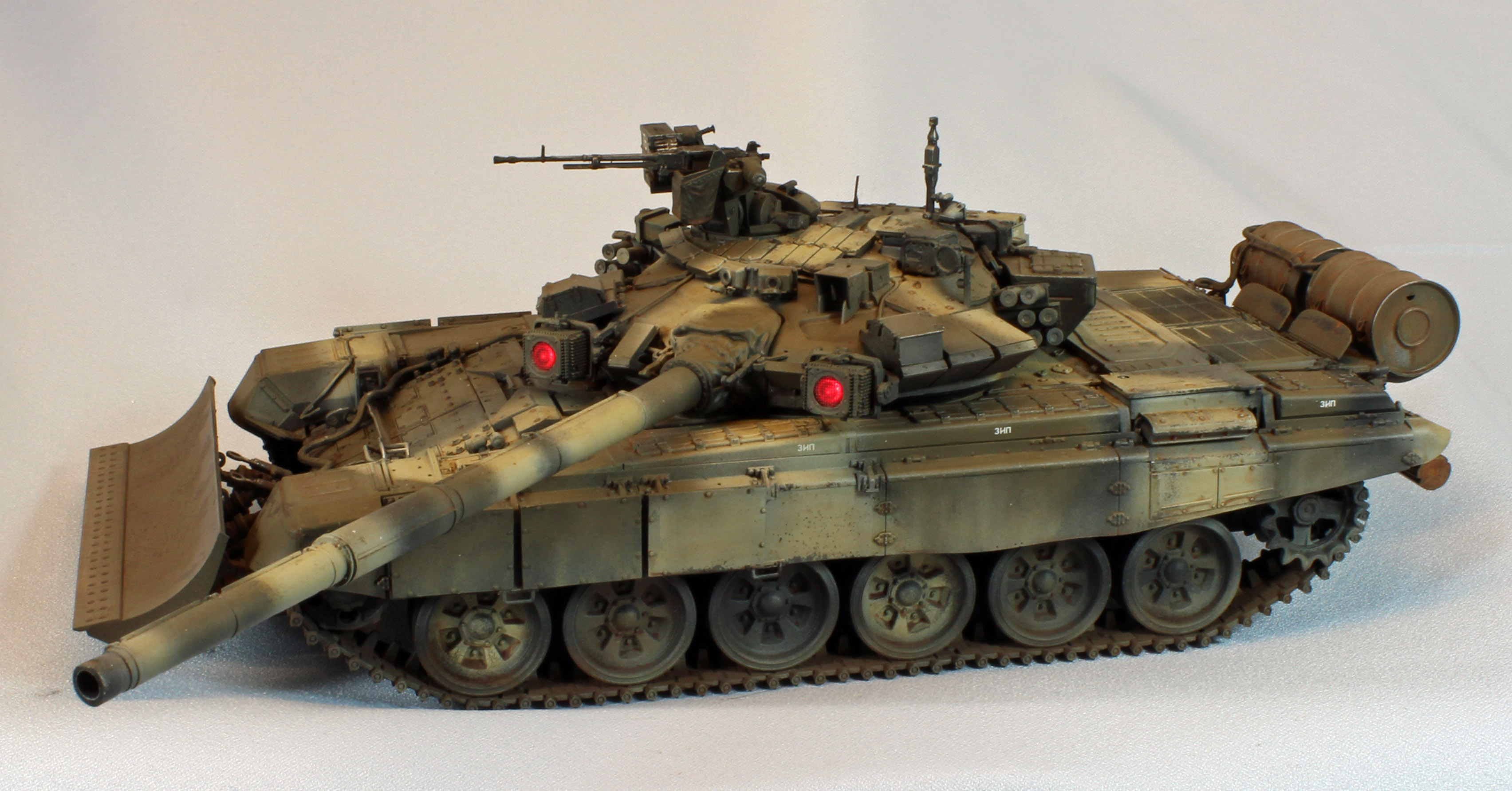
Meng has released a second version of their excellent T-90A, this one with newly designed track and two optional front ends: a self-entrenching device, or a TBS-86 Tank Dozer blade. The twin electro-optical/IR ‘dazzler’ lights come complete with all electronic bits to make them light up, and a layer of nylon turret (composite armor) ‘skin’ add to an already interesting build. The T-90 tank is protected by both conventional armor-plating and explosive reactive armor, and fitted with the Shtora-1 defensive-aids suite which includes an infrared jammer, a laser warning system with four laser warning receivers, a grenade discharging system which produces an aerosol screen and a computerized control system. It is also fitted with NBC (nuclear, biological and chemical) protection equipment. Altogether, the T-90 represents state-of-the-art Russian armor, and Meng has produced a masterpiece representing it in scale.
Opening the Box
This kit is packed to the brim with a host of modeling mediums, including plastic sprues, nylon skins, electronic parts, photo-etch, string, a painting template, poly caps – the works. The sturdy box bottom is manufactured using some kind of very tough material – it almost feels like molded 1/16th inch white styrene. While I managed to damage several delicate parts during the build, they arrived from Meng fully intact and protected. The plastic contains a small amount of flash, noticeable in the dozer section, and there are several prominent pour stubs that will have to be addressed.
- Upper hull, lower hull, and turret packaged separately.
- 13 sprues in soft, dark green plastic, packaged separately.
- 2 clear plastic sprues
- 1 sprue of nylon parts that comprise the outer skin of the turret
- 1 sprue of poly caps
- 20 small sprues of track pins
- Track assembly tool
- Suspension-positioning tool
- 1 small box of electronic parts and wire to light up the dazzler lights.*
- 1 package of single-piece track links (200 links)
- 1 nylon gun mantlet
- 1 large photo-etch sheet, containing 15 parts
- 1 paint template for painting the wheels
- A length of string for tow cables
- 1 30-page instruction booklet with 54 steps
- 1 large and perfectly registered sheet of decals of unknown origin
Many of the parts are very, very thin and delicate. While everything arrived intact, I managed to break several parts removing them from the sprue, although you can tell that Meng has worked hard to position the sprue attachment points as unobtrusively as possible. In many places Meng has thoughtfully printed the part number in tiny letters on pieces that look nearly identical but are not. The part numbers are not visible once attached. This is especially helpful when attaching the myriad of reactive armor pieces on the turret.
The instruction booklet is another example of the beautiful work we’ve come to expect from Meng. Up front is an extensive, yet summarized history of the vehicle, as well as a biography of the Chief Designer, Vladimir Potkin. The 54 steps rarely involve more than a dozen pieces, and the CAD images are useful and easy to follow. I did not find a single mistake throughout the build, although there were several areas where I wish Meng had included more CAD images, or images from different points of view, especially in the 20 steps (!) encompassing the turret. One thing that Meng chooses to do that I wish other high-end manufacturers would do, is to name the subassemblies in the instructions so the builder has some idea of what they’re building (so THAT’s a ‘Crosswind Sensor’ – who knew?)
Curiously, I could not find a list of unused parts, and there are quite a few of them.
The kit comes with four pages of full-color, five-view drawings representing three color schemes. These include:
- 108th Tank Regiment, 5th Guards Tank Division of the Siberian Military District
- 467th Training Center, Korov
- 38th Research Institute in Kubinka, Tanker’ Day Celebrations
Things to consider before building:
I have heard it suggested that you should skip ahead to Step 47 and build the dozer blade section first, which I did, but when I got to attaching it later on I didn’t think that skipping ahead was necessary after all. On the other hand, the dozer blade assembly is fiddly and comes right on the heels of 20 grueling steps assembling the turret. Needless to say, I was relieved to have had already finished the dozer section when I finally got to it.
The side fenders are attached in Step 21, and depending on how you completed Steps 13, 15 and 20, large gaps might appear, as was the case with my build. The front and rear mud guards need to match up with the side fenders precisely, so I suggest that you assemble the fenders in the following order, before the glue sets:
(Do one side at a time)
- At the end of Step 13, attach (one) front fender to the upper deck.
- omplete Step 20 for the same side, leaving off the delicate side-armor attachment hardware (F17, B25, F4, etc.), and attach it to the upper deck and the front fender.
- Attach the rear fender (Step 15) to the upper deck and side fender.
- Line everything up and let it dry fast, then repeat for the other side.
- Once both sides are dry, continue on from Step 13.
The Build
The build begins with the lower chassis and running gear. The twin sets of wheels come with a poly cap insert and slip onto a brilliantly-designed torsion bar system, the fit being perfect. Meng includes a very handy alignment tool that is used once all the torsion bars are in place. Just slip the tool over all the bars and you can move them in unison to the position and height desired. Once set, apply glue to the bars, wait for everything to dry and slip off the tool. Snap.
In Step 5, a mud scraper is attached to each side, just behind the drive sprocket. I thought I had attached mine correctly, but later, in Step 8, the scrapers interfered with the fit of the track runs, requiring a little emergency surgery. Other than that one minor issue (which was most likely self-inflicted), the fit and engineering was so good that I had completed the entire lower chassis and the track in a single two-hour session.
The initial release of the T-90A had a relatively complex track assembly, with multiple parts per link, and thereby creating a lot of busywork for the modeler. Meng went back to the design lab and returned with a new approach – single-piece links that are held together using tiny pins pushed in from the outside using a handy tool included with the kit.
Alas, the promise of workable track is there, but the engineering comes up a little short. The tiny pegs meant to hold the links together are simply too small, and actually end up getting in the way when manually connecting the link sections. The tool used to assemble each section of six links leaves the links connected only on one side, and each section when put together with the one next to it, leaves a slight, but noticeable gap. I ended up manually scraping off all the tiny pegs and assembling the track ala Dragon’s MagicTrack – which, compared to Meng’s initial version of the T-90 – was a cakewalk. I had both runs completed in a little over 40 minutes.
The instructions call for 96 links per side, and I felt that was about one link short. Luckily, the fenders hide the gap. I had 17 links leftover.
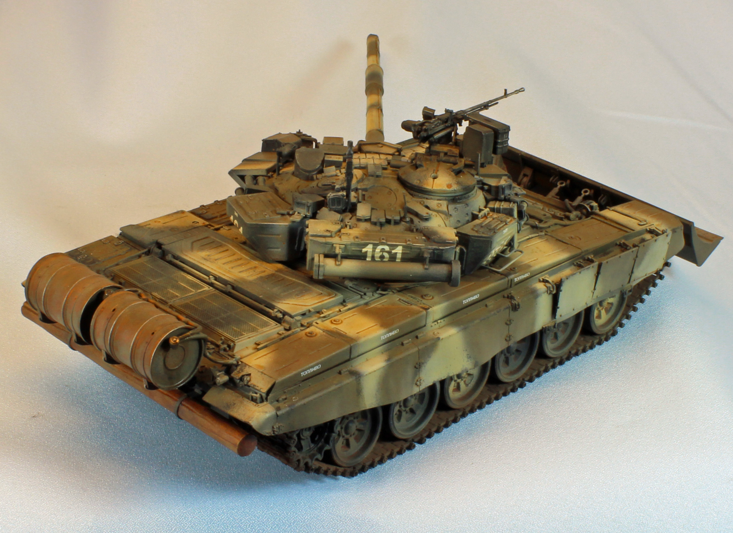
The main deck starts to come together in Step 9. Everything fits very well, and the delicate power cables and such slip right up, around and under where they are supposed to go. Fun! You are given the option of using photo-etch mesh for the engine intakes or cover them with NBC armor.
The fit and design of the fenders are brilliant. Unfortunately, I let the front and rear mudguards (Parts D33 and D34) dry hard before attaching the side fenders, requiring me to muscle the mudguards down onto the fenders afterwards. You can avoid this problem if you follow the suggestions made in the ‘Things to consider…’ section, above. The brackets for the two (optional) fuel drums are attached in Step 17. The attachment points on these are not very sturdy and I had to fiddle with them while they dried to make sure they remained lined up.
Warning: In Step 20, Parts F24, B24, B25 and F17 must be attached and horizontally- aligned perfectly. While the design of the fenders is brilliant, you really need to pay attention here. These parts are what the three prominent armor plates that swing outwards from the fenders attach to later on in Step 21. The three rectangular plates have noticeable vertical and horizontal lines on the finished model, one stepping up from the other beside it. Unfortunately, I let the glue dry on the attachment hardware in Step 20, and one of the parts was not aligned perfectly with the others, causing me, in the end, to simply attach the armor all in a line on both sides. Trying to fix the problem simply broke more parts, which are extremely delicate, making things worse. My bad. Heed the warning.
In Step 22, attach Parts F23 and the two cables before the wood log. I could not get the over-scale and ‘fluffy’ string included in the kit to play nice with the cable ends, so I left the cables off. With so much else included in the kit, twisted wire for the tow cables would have been much appreciated.
What initially appears to be a complex task ends up being just the opposite. Pay attention to the orientation of the two drums so that parts C46 and C51 end up on the correct side. After that, the two spaghetti-style plastic cables fit perfectly against the drums – they can only go one way. Great design, Meng!
The T-90 turret is quite a production, both on the real vehicle and in the kit. A full 20 busy steps are taken up just to add the detail provided in the kit, starting with the barrel in Step 25. The eight-piece barrel has plastic seam lines that follow the natural lines in the steel, leaving a small seam along only part of the underside and out of sight. There may be after-market barrels available but I can’t see the need – Meng has a good design here.
Each step adds another layer of detail over the previous steps. A slow and methodical approach helps here. I had to enlarge some of the holes to attach things, and I discovered that if there is no receiving hole, then I had done something wrong – the design is that good.
Meng includes a sprue of flexible vinyl parts representing composite armor for the turret. I’ve encountered this material before in other Meng kits, and it is a little disconcerting - your brain tells you that it shouldn’t work, yet it does. I glued each piece to the turret using Model Master (black label) liquid cement, and then touched up any loose edges with Tamiya (green cap) liquid cement. I held each piece in place for a few seconds and it stuck to the plastic like a second skin. I can’t figure out why Meng just didn’t mold the detail into the turret to begin with, but the fit is so good with these vinyl pieces it doesn’t matter either way. As a bonus, if you manage to lay a piece of vinyl on upside-down, (like I did - Part T12), you can peel it off, clean things up, and glue it down again - even after it’s totally cured. Try doing that with plastic!
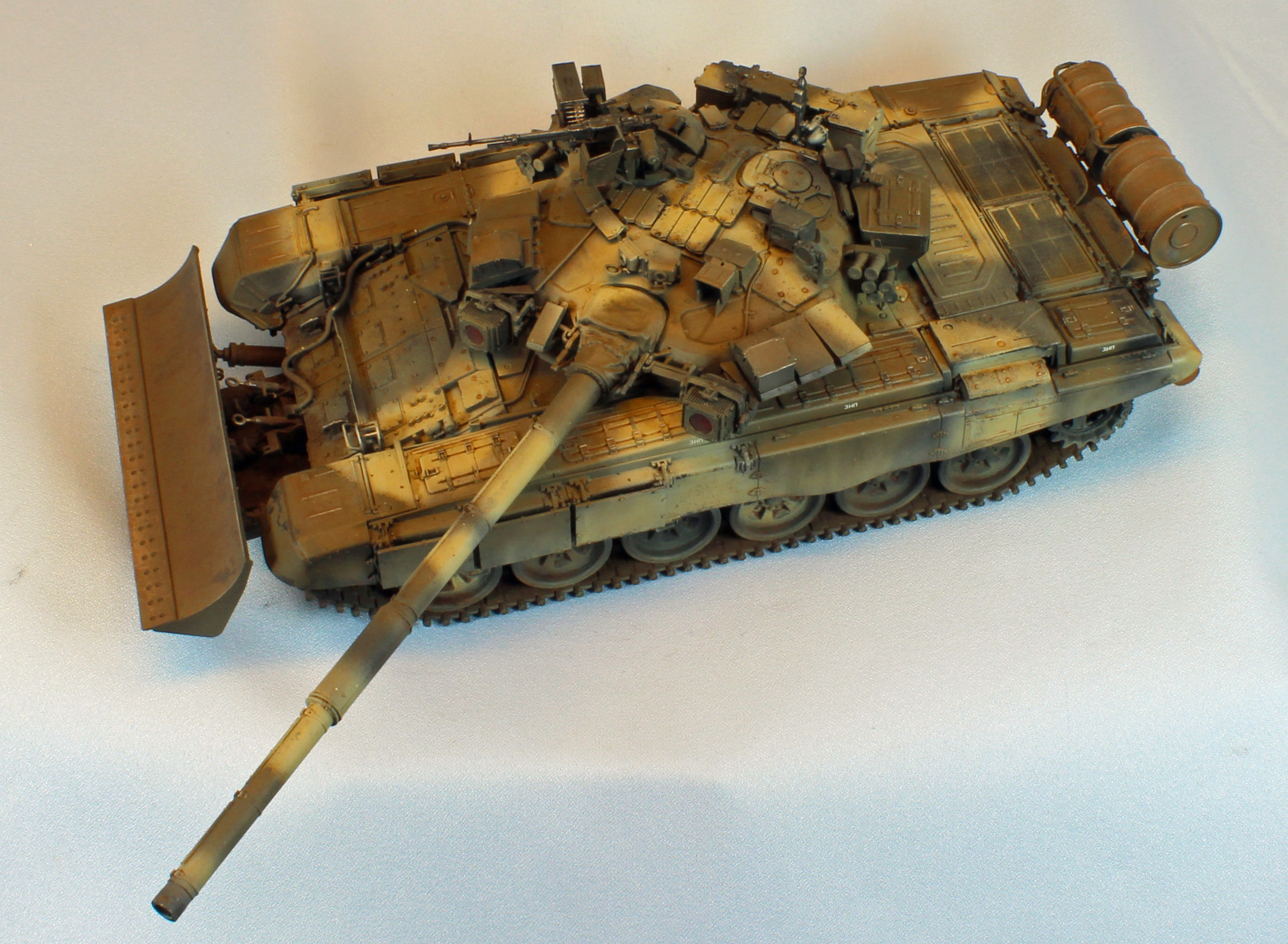
The gun mantel that holds the barrel slips inside a really nicely detailed vinyl cover, but take care when gluing the mantel to the turret. If you attach it as shown, the barrel will be pointed upward in a very un-combat looking ‘parade’ angle. I slid mine down just a bit, opening up and exposing an un-detailed portion of plastic that looks odd, but not as odd as that upward barrel angle.
There are two nice little control panels that extend downward from the top of the turret. The panels are visible if you leave the two hatches open.
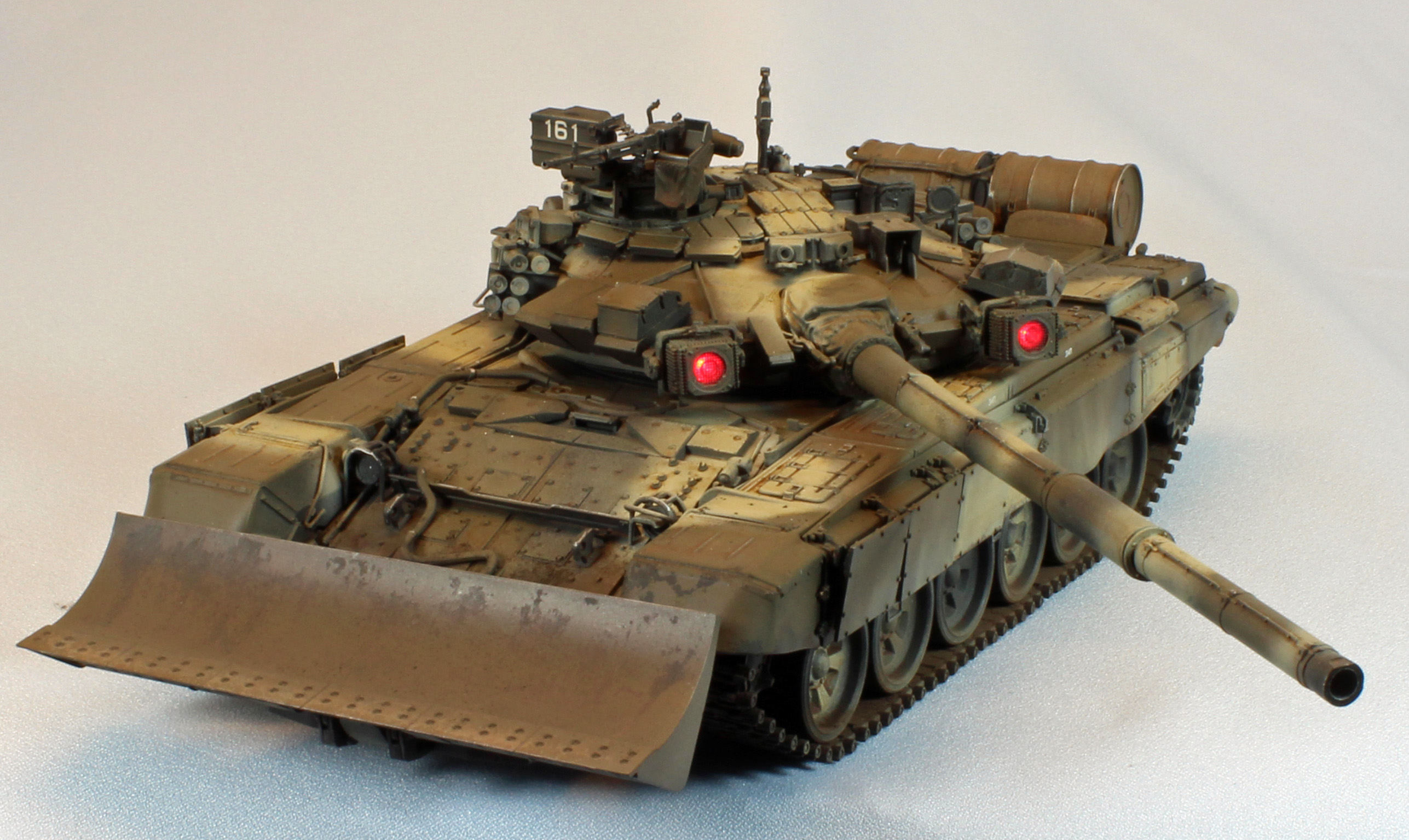
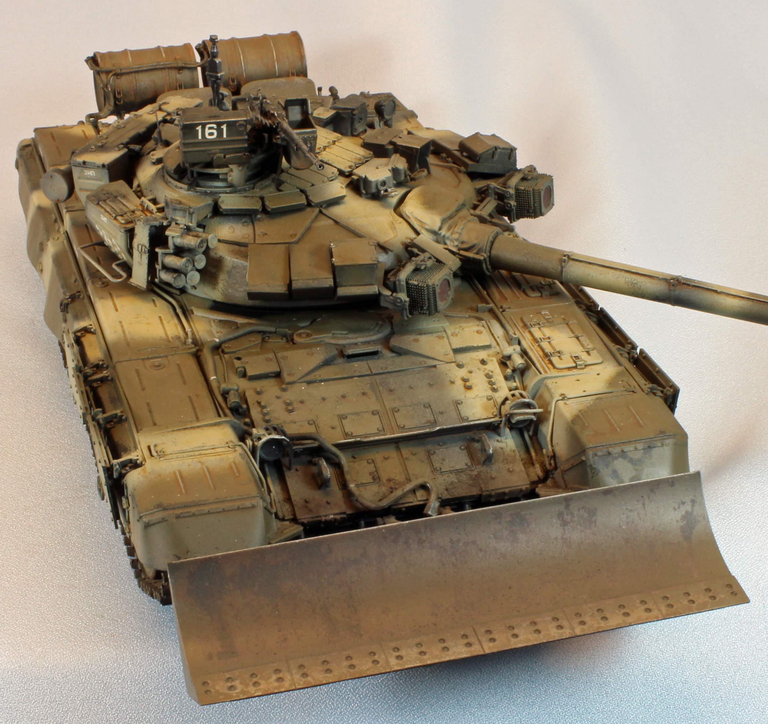
Steps 32 through 35 are the toughest in the build. This is where the two dazzler lights are assembled and attached. The fit of everything is sound – that’s not the problem. The articulated design results in a delicate and weak connection, and if anything is backwards or upside down, you won’t know it until the very end. I really had to study the images carefully, and even then I had to do several things over. In the end, however, everything came together. The battery package kept pushing into the turret interior as I handled the turret to attach parts so I had to use 2-part epoxy to secure the hard-plastic case that holds the battery case to the turret, all other types of adhesives failed to work with this plastic. Likewise with the button switch, which also kept pushing into the turret.
I painted the infrared lights (Parts K2) with Tamiya Clear Red before sandwiching them between Parts R18 and G12. Later, I applied liquid mask to these lights so they would still ‘dazzle’ after painting and weathering.
Note: Removing this mask was a problem – the bumpy texture of the lens caused the mask to hold fast, and nothing I had could scrape or pull the mask off. A quick trip to the store to purchase a square chunk of rubbery material called ‘Rubber Cement Pick Up’ solved the problem. The mask stuck to it like warm chewing gum and lifted right off.
Next came the big stuff – Steps 36 through 45 involve creating sub-assemblies and then attaching them to one place or another on the turret. Meng describes each sub-assembly for you so you get to learn a lot about the tank as you work – very cool.
These steps went along fine until I hit the anti-aircraft machine gun – specifically Steps 43 and 44. No matter how I arranged the parts, nothing seemed to fit right. I ended up sort of ‘smashing things together and adding glue’ until it looked like a gun. To mount the weapon on its pedestal, I actually created a little three-part cage of plastic bars to support everything, making sure it stayed out of sight. Sometimes you just have to do a little modeling I guess.
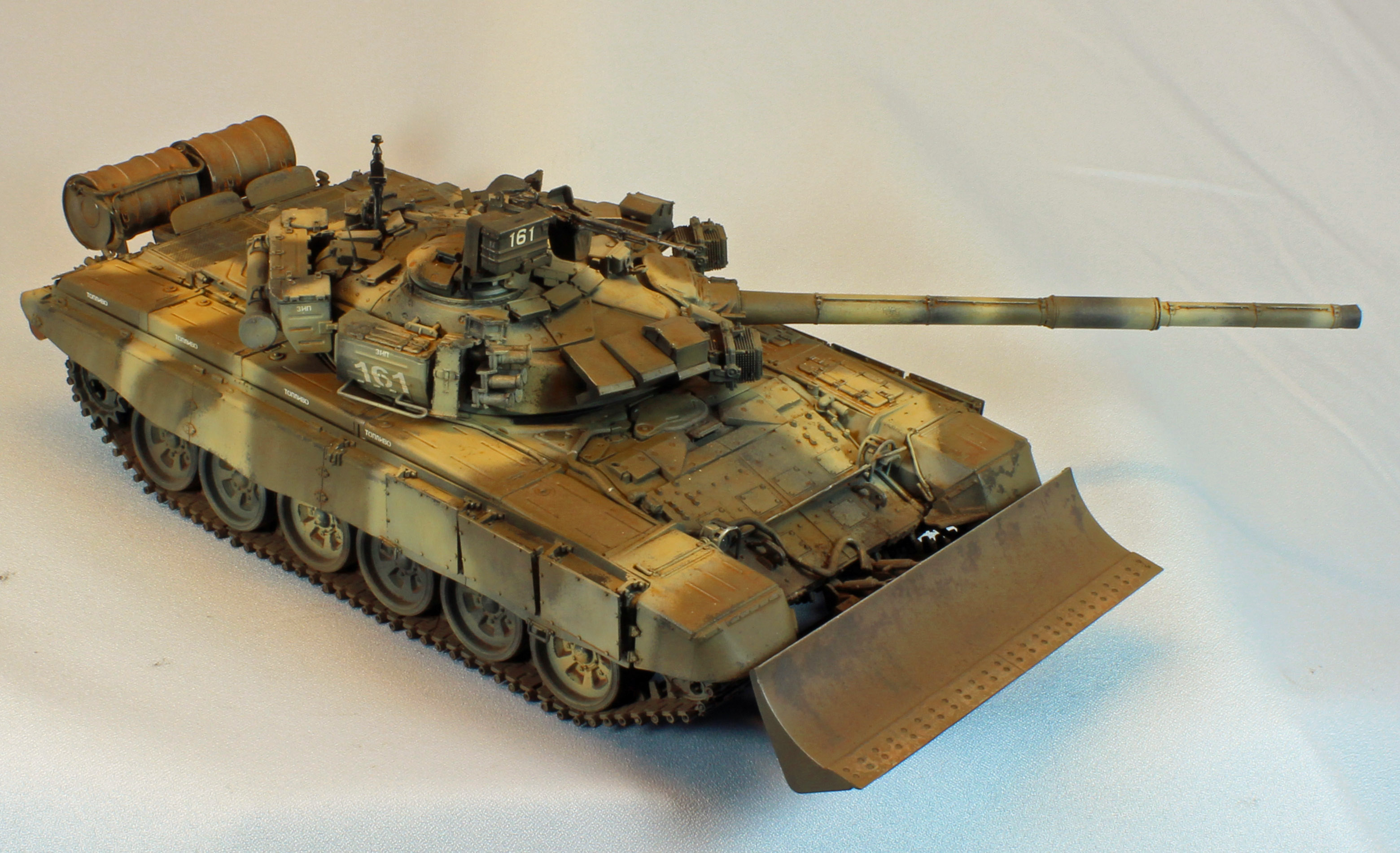
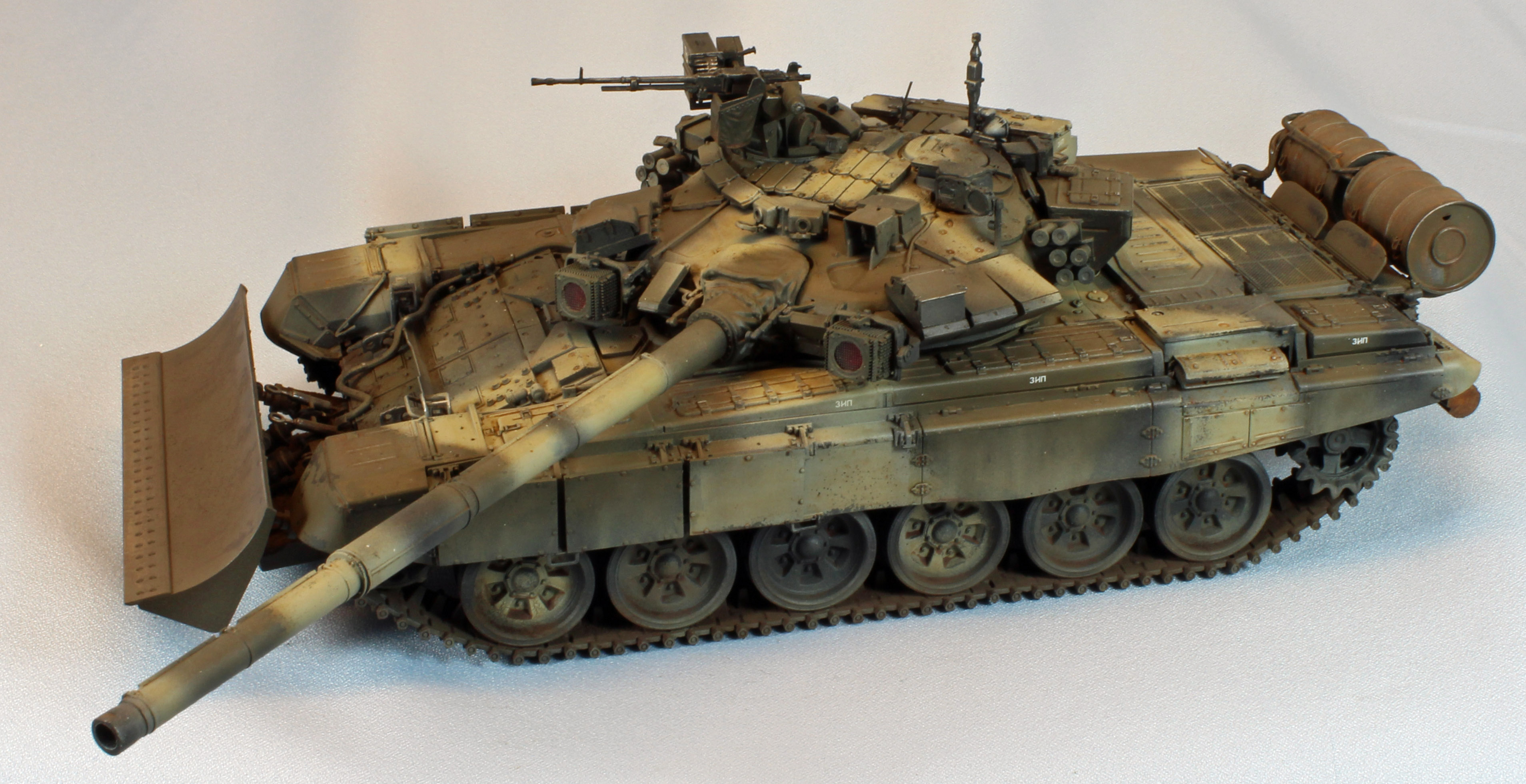
This release added two options for the front of the T-90; (1) a self-entrenching device that can be shown in the extended position or glued up against the underside of the tank, or (2) a detailed TBS-86 Tank Dozer blade that can be shown in several positons. I had originally planned to build the dozer section, temporarily attach it, take pictures and then remove it before putting the finished model in its resting place. Once I saw the beautiful detail, however, I kind of got used to the look of it up front. This is one busy tank!
The dozer blade itself comes together easily; the hardware that attach it to the tank and move it up and down is another story. Again, the fit is good, but the design is complex, and a lot of that has to do with the fact that everything is articulated. Even if you plan to glue the blade in a single positon, you still have to build the articulation into the thing just to get it to where you need it. By the time I got to step 50, where no less than six photo-etch covers are added, I was beat and decided to leave them off. I figured they would be the first casualty in combat, and they covered up some really nice detail that I wanted to remain visible. The last step was to attach the long, twisting nylon power cable that went from the front of the tank to the dozer section. As expected, it fit perfectly. This big bad boy was done.
Painting and Finish
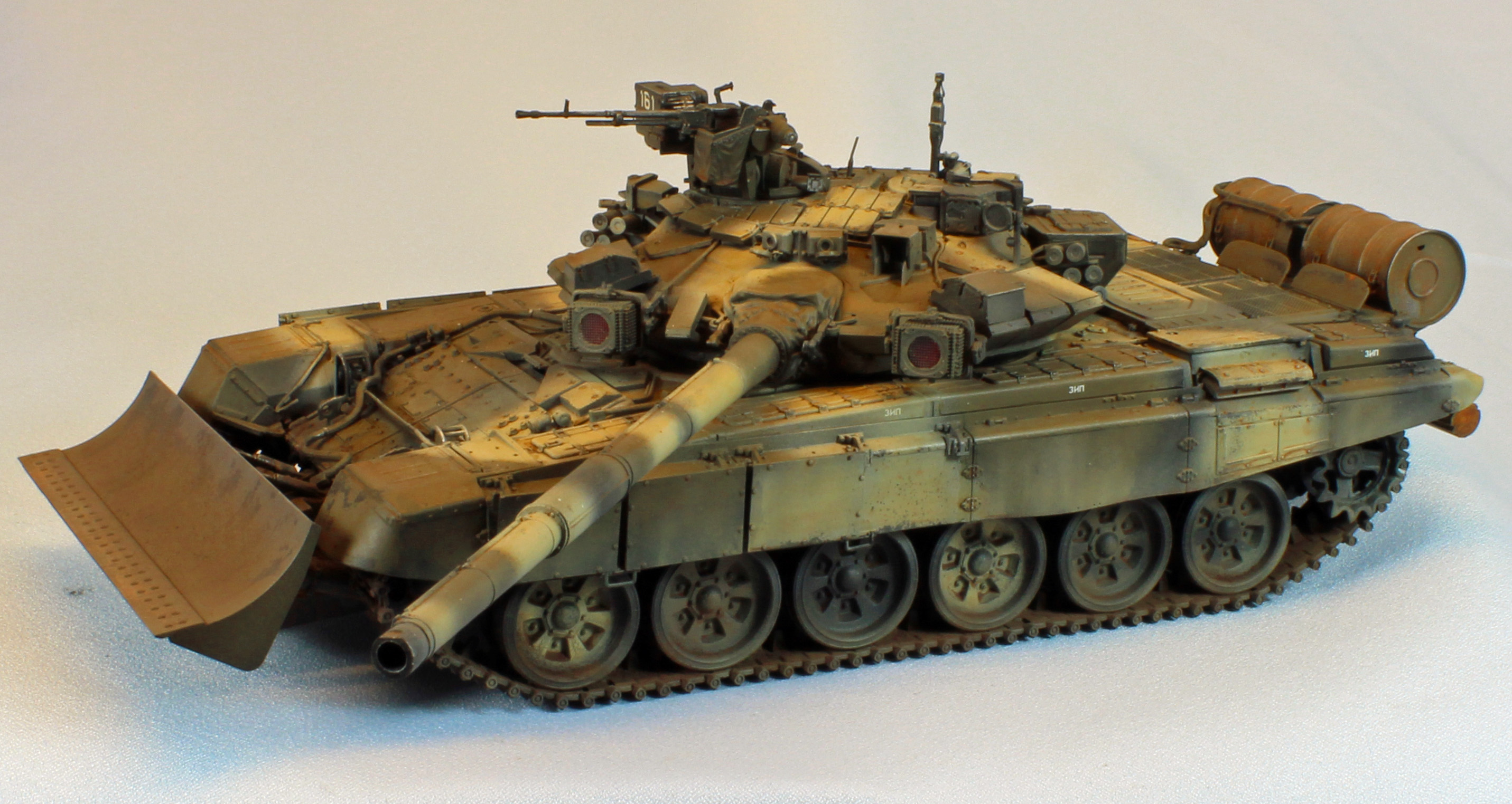
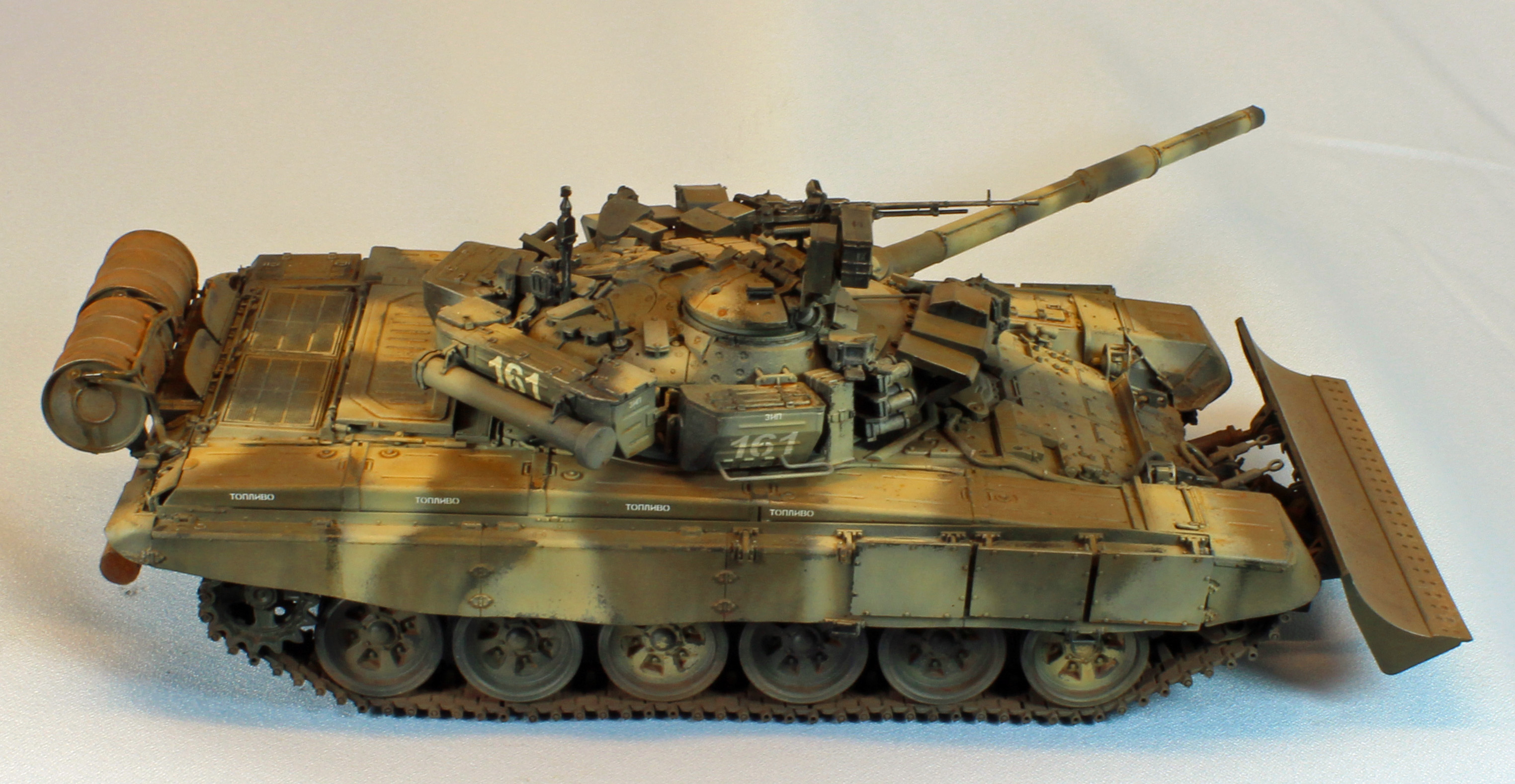
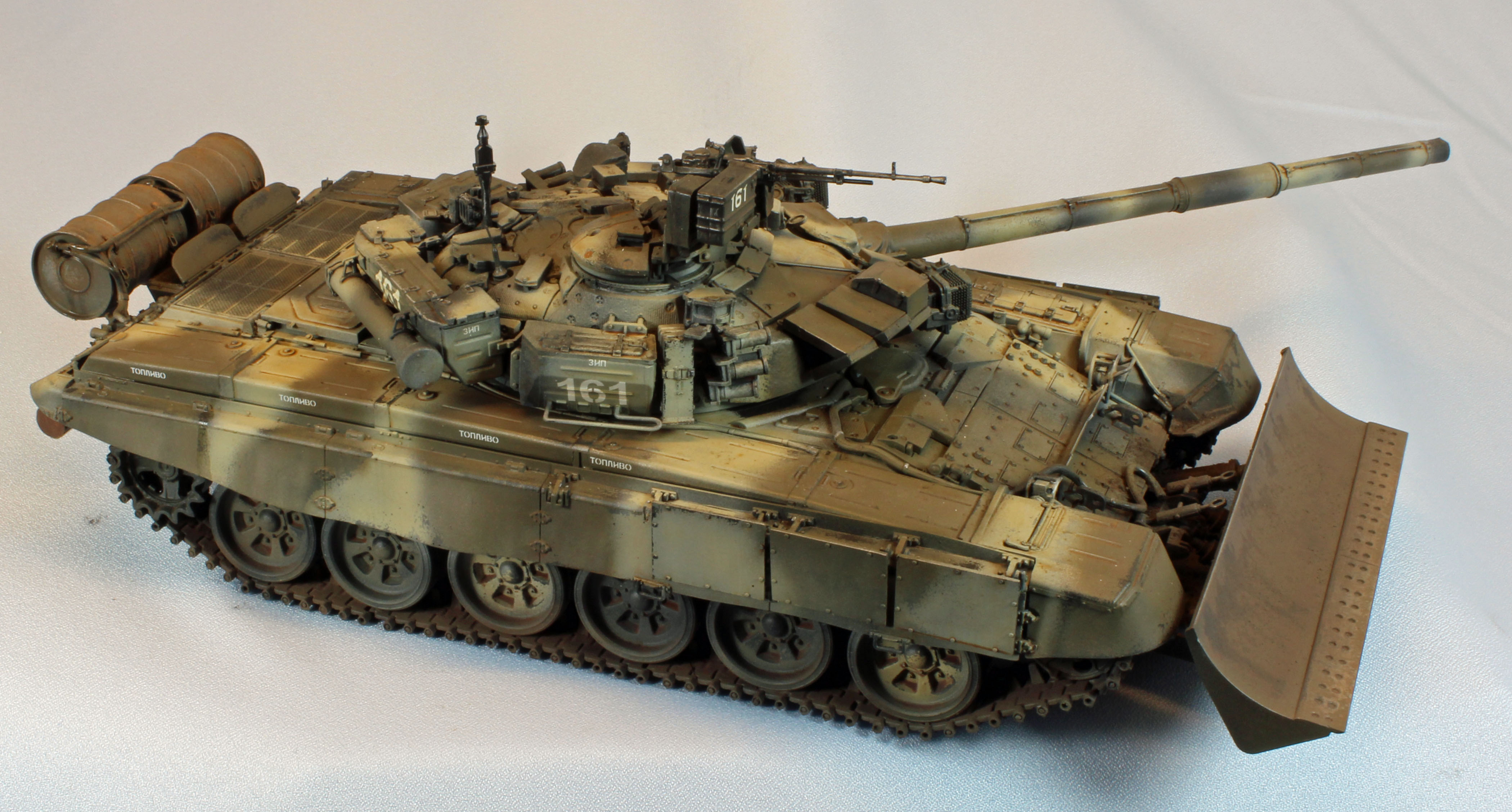
I saw a beautiful T-90A at a recent show and decided to finish mine in the same way, using a slightly modified version of the first scheme in the instructions (108th Tank Regiment, 5th Guards Tank Division of the Siberian Military District). I wanted to use the hair-spray method for paint chipping and to dirty up the dozer section, so my work was cut out for me. Since I modeled the hatches closed, I was able to finish the entire kit before starting to paint and weather it.
I started by airbrushing a primer/pre-shade coat of Gunze Mr. Finisher 1500 Black to give the plastic and PE some grip for the following coats, and to fill in the recesses and create a shadow effect near the flat surface edges, adding depth for the subsequent coats to come. I really like Gunze’s new product – it goes on beautifully when thinned with their Leveling Thinner and combines what used to be two coats of paint applied in two painting sessions all into one. I allowed that to sit overnight to de-gas. Once the paint was dry, I sprayed the dozer blade with Tamiya XF-9 Hull Red and used Tamiya XF-16 Flat Aluminum for the ‘conformal’ fuel tanks along both fenders, the fuel drums and the front edge of the dozer blade.
Once that was dry, I gave the surface of the entire vehicle a pretty heavy dose of hairspray to seal the pre-shade colors. I use TreSemme pump-spray for the job, but I don’t think it matters. Once I let that dry for about 5 minutes I proceeded on to the camouflage step.
In my eye, the tri-color camouflage of the T-90 does not make it look like a green tank with tan sections, or like a tan tank with green sections. It’s kind of a mix of everything, so I had to make sure that one color did not dominate any other.
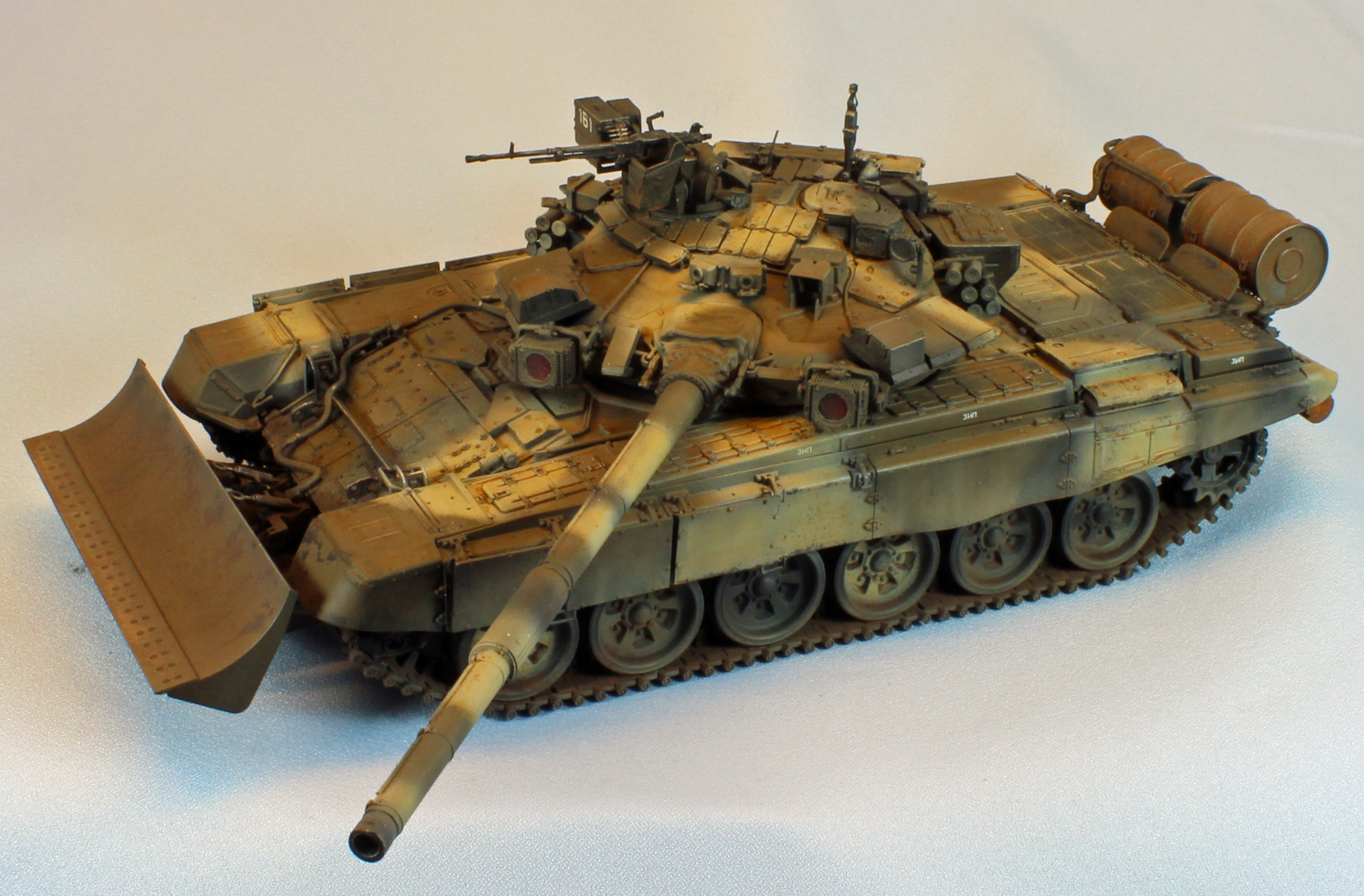
I laid down a wavy camouflage coat of Tamiya XF-62 Olive Drab lightened with Tamiya XF-15 Flesh for the green color, and Tamiya XF-55 Deck Tan, in that order. I painted the fuel tanks and the dozer equipment using the green mix – most of the paint there would be rubbed off. I let the camouflage coat dry for about four hours, and then took a short horse-hair brush and a cup of water and went to work on the surfaces of the turret, hull, wheels, fuel drums and especially the dozer blade. You can easily go too far with this, so I tried to build up the paint chipping a little at a time until I was satisfied with what I had.
Once the paint was dry, I hand-brushed Future over the areas that would receive decals. I applied the decals using the Red and Blue Micro Sol/Set system without any problems, followed by an additional layer of Future to seal them.
I then sprayed a light coat of Vallejo Matt Varnish to kill the shine and prepare the surface for filters.
I applied an overall filter of Mig Wash Brown, using AK Interactive Track Wash on the track, and a Mig 110 Black filter on the engine grills. I thin all of my washes and filters using Mona Lisa Odorless Thinner, which will not affect underlying layers of paint.
I applied a pin wash of Mig Dark Wash (aka Raw Umber) straight from the bottle using a small red sable brush, concentrating on the panel lines, recesses, rivets, buckles, on-board equipment, etc.
(Note: For hand-brushing Vallejo paints, I put a drop of Vallejo Slow Dry and a drop water onto an old CD and then single drop of all the colors I need. I mix the colors with the water and slow dry until the paint flows smoothly off a red sable brush.)
I left the main barrel of the machine gun black from the pre-shade step, went over it with a silver quilter’s pencil to highlight the protruding parts, and then hit it with all the washes and filters as I went along. I painted the ditching log Vallejo Old Wood, and when dry, brushed a layer of Mig Wash Brown straight for the tube over the ‘wood part’. The next morning, I used a Q-tip to remove just enough oil paint to make it look right.
Finally, I applied a ‘road-dusting’ coat consisting of Vallejo Light Brown followed by a coat of Vallejo Flat Varnish to kill any shiny spots still remaining. I cut each of these 50/50 with Vallejo Airbrush Thinner and a drop of Liquitex Flow Aid to improve flow. Once everything was dry I dusted some Mig Russian Earth and Black pigments on the sides of the armor here and there, as well as the track to rough the visible surfaces up a little.
Conclusion
Meng produces great kits, and some of them, like their T-90A are quite a challenge. There are layers upon layers of detail on the real tank, and Meng pulls no punches replicating them here. Like most of their other kits, the parts fit and are beautifully detailed; together making for an interesting build.
That said, this kit has its moments. Even though the track has been re-designed from Meng’s previous release, it will give you problems unless you simply go with your experience using individual-link track. The turret assembly seemingly goes on forever, with a zinger at the end in the form of an ill-fitting AA machine gun. Finally, the built-in articulation is fiddly for both the dozer blade hardware and the ‘dazzler’ IR lamps, articulation that you must complete in order to see where things will be glued down permanently.
Still, the challenges are surmountable and the result is a fine-looking model and an excellent representation of the real thing. I recommend this kit to all modelers who have experience solving minor problems. Open up your schedule a little and consider the suggestions above. You won’t be disappointed!
I would like to thank Meng Models & MMD Squadron for providing this kit for review, and to IPMS USA for giving me the opportunity to review it.
Photos