Reviews
Aircraft
Hawker Typhoon Mk.IB
by Eric Christianson
 Model: Hawker Typhoon Mk.IB - Part 2
Reviewed by: Eric Christianson, IPMS # 42218
Scale: 1/24
Company: Hornby Airfix
Price: $149.99
Product/Stock #: A19002
Website: Airfix
Product Web Page: View
Product provided by: Airfix
Part One of this review can be found here:
http://ipms-seattle.org/reviews/aircraft/2015-EC-Airfix-19002-Part1/
Part Three of this review can be found here:
http://ipms-seattle.org/reviews/aircraft/2015-EC-Airfix-19002-Part3/
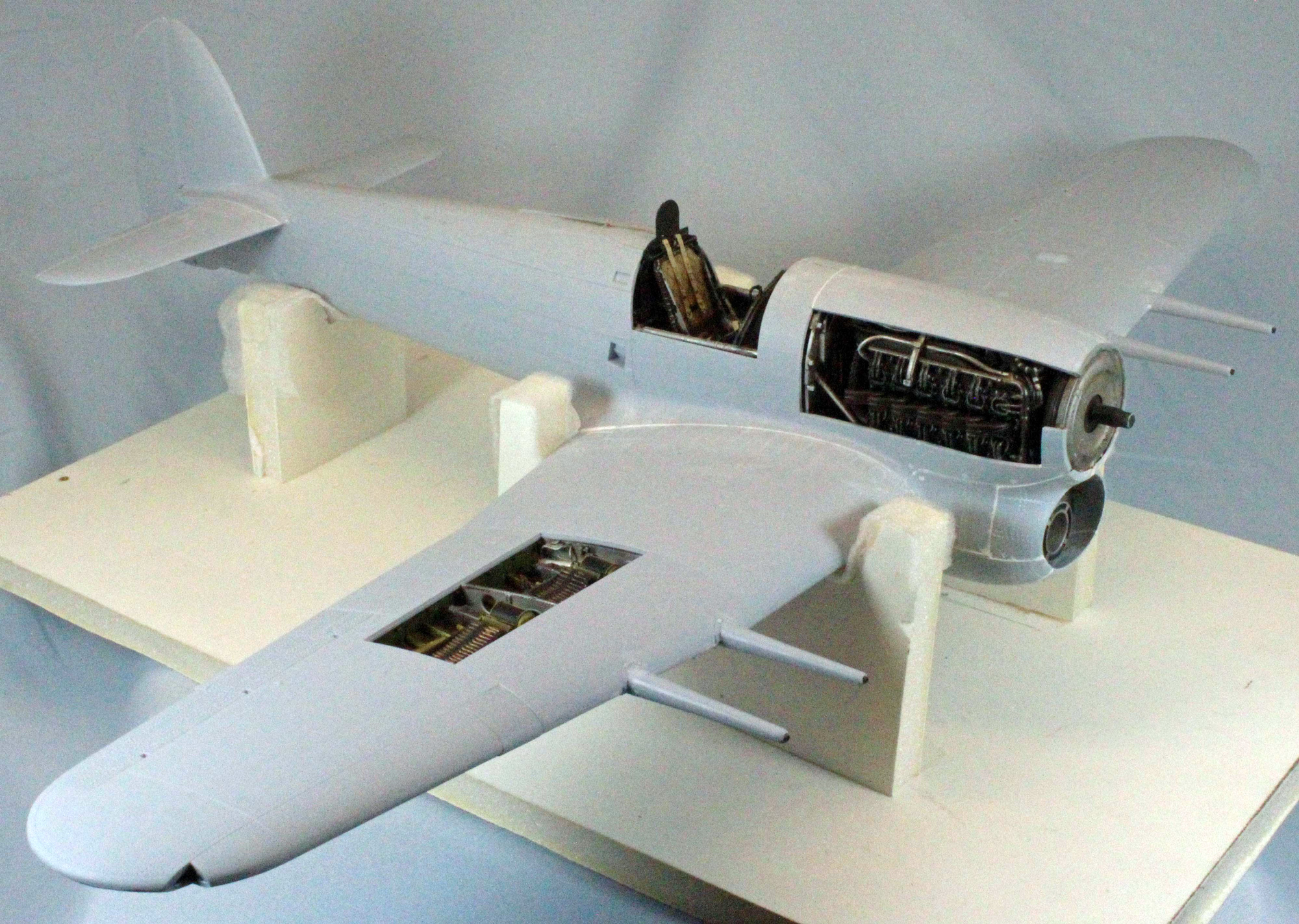
Welcome back! Last time we had just completed the internal framework, engine, lower front end and cockpit of the big 1/24th Scale Airfix Mk.Ib Typhoon. This second installment will bring the wings, fuselage, nose and wheel-wells together, leaving the final assembly and finish for the last segment of this three-part review. To recall: I chose to expose only the starboard wing’s gun bay and starboard engine detail, and to cover up the lower front end encompassing the oil cooler/air intake.
Work is going along very smoothly, with a single exception being the front end of the aircraft. Whether the problems I encountered were self-inflicted or due to some flaw in the kit remains to be determined.
More on that later – for now, let’s get back to work!
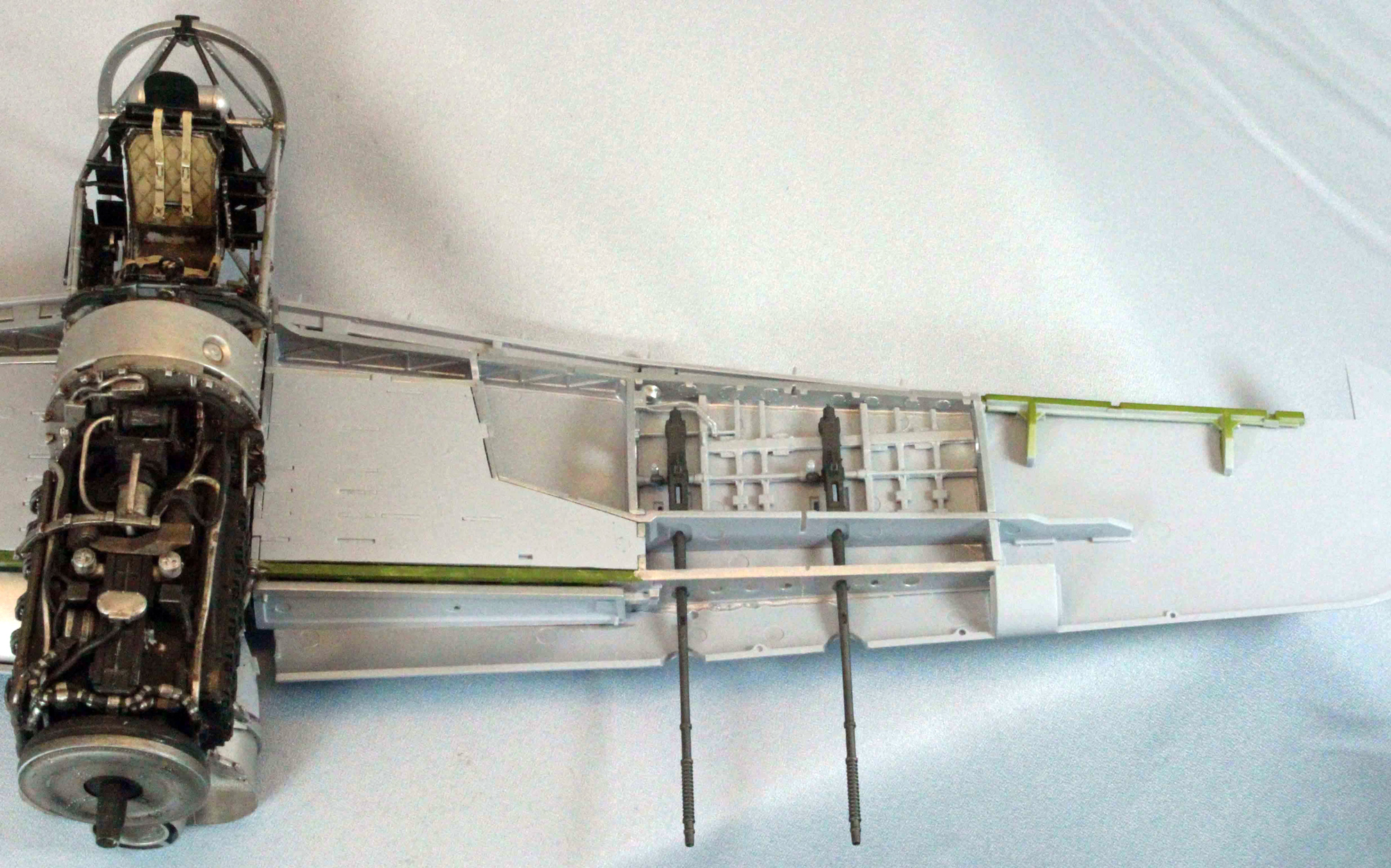
The Wings
The wings of the Typhoon are substantial, and Airfix chose to put a lot of structure into the kit even though much of it will be covered up on the completed model. Looking at my references and what Airfix specifies in the instructions, some parts are interior green, some flat-aluminum, some a yellow-green and some a port-wine colored leather (!). Access is limited so visualizing what ends up exposed vs. what is covered up is vague at best, so before I started Step 92, I painted the following parts:
- Forward and Rear Main Wing Spars Model Master 1715 Interior Green, leaving the center section Tamiya XF-16 Flat Aluminum.
- Lower wing cannon bay sections of the wing (that will be exposed) Vallejo Panzer Aces 312 Leather over a pre-shade of Tamiya XF-69 NATO Black.
- Gun racks (Parts F38/F39) Tamiya XF-4 Yellow Green over a pre-shade of Tamiya XF-69 NATO Black.
- If you plan to drop the flaps on the back of the wings (I didn’t), paint the exposed parts of (F13/F14) Model Master 1715 Interior Green.
- All the internal cross panels (Parts F02, F36, F23, F18, F-37, F29, etc.) Tamiya XF-16 Flat Aluminum. While I had the aluminum loaded up, I painted the backs of the long fuel tanks (Parts G12/G13) as well, since these can be seen in the finished wheel wells.
I started by drilling out the holes in the lower wing needed for the wing stores. Each scheme in the instructions requires its own holes so check your references here. Assembly was simply amazing. Each piece of the wing structure in Steps 88-110 slipped into the parts surrounding it like a glove. Even though the fit was excellent, I didn’t want to take any chances. I used a variety of clamps to hold the lower wing to the bottom of the engine/cockpit/wing spar assembly to insure that the upper wing fit later on. I took this opportunity to lay down a little weathering around the gun bay and exposed aluminum, using a wash of Mig Wash Brown diluted with Mona Lisa Thinner.
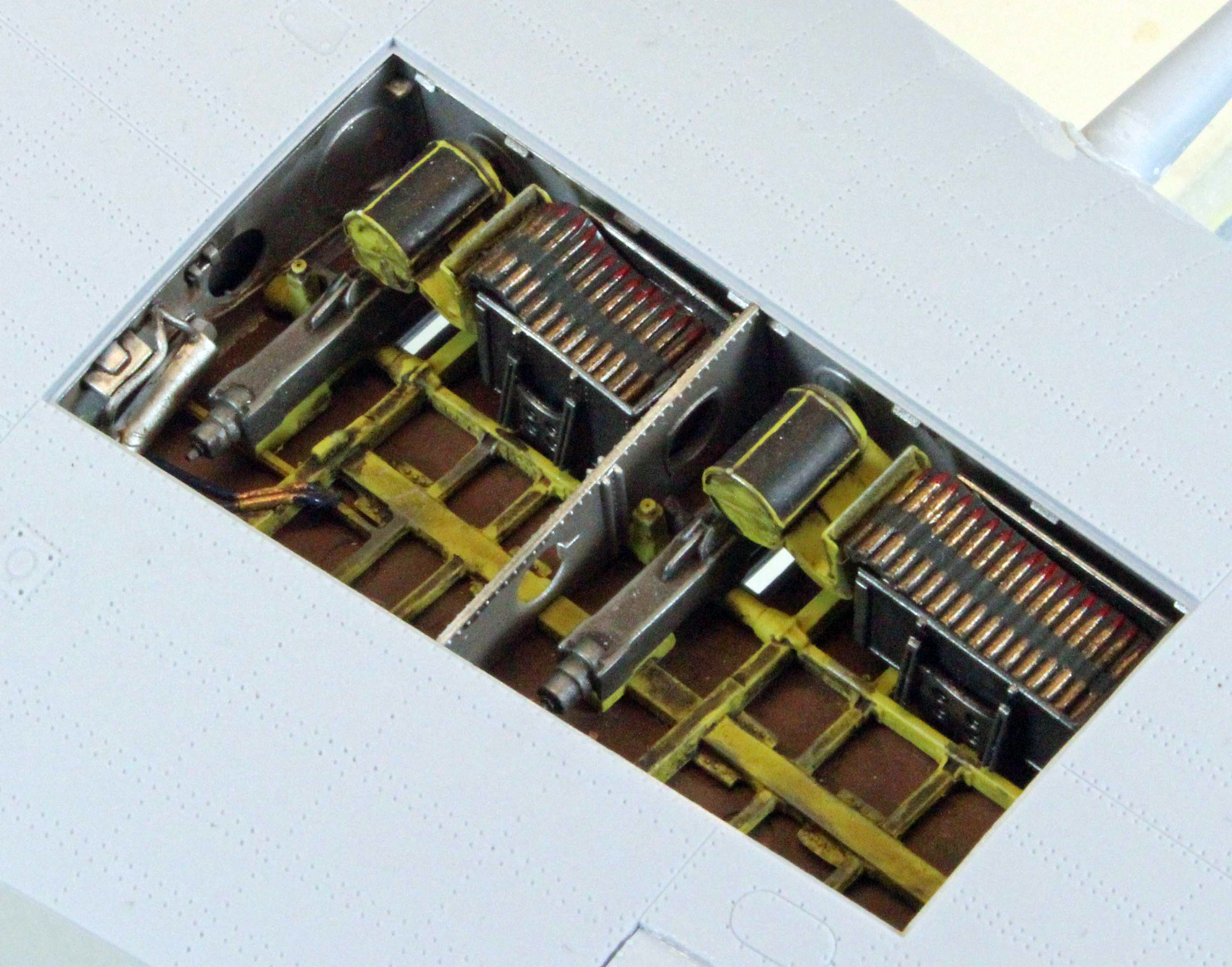
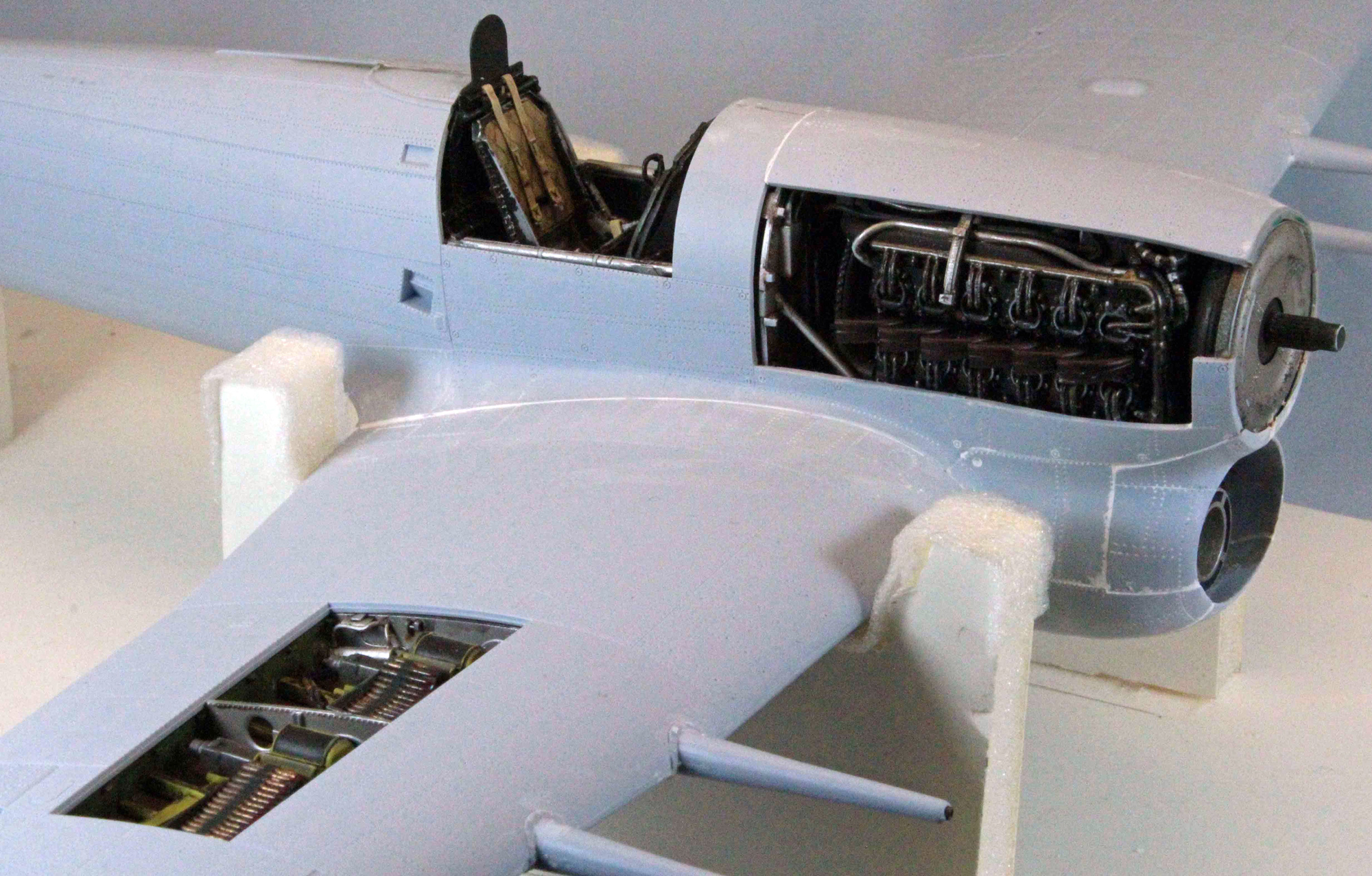
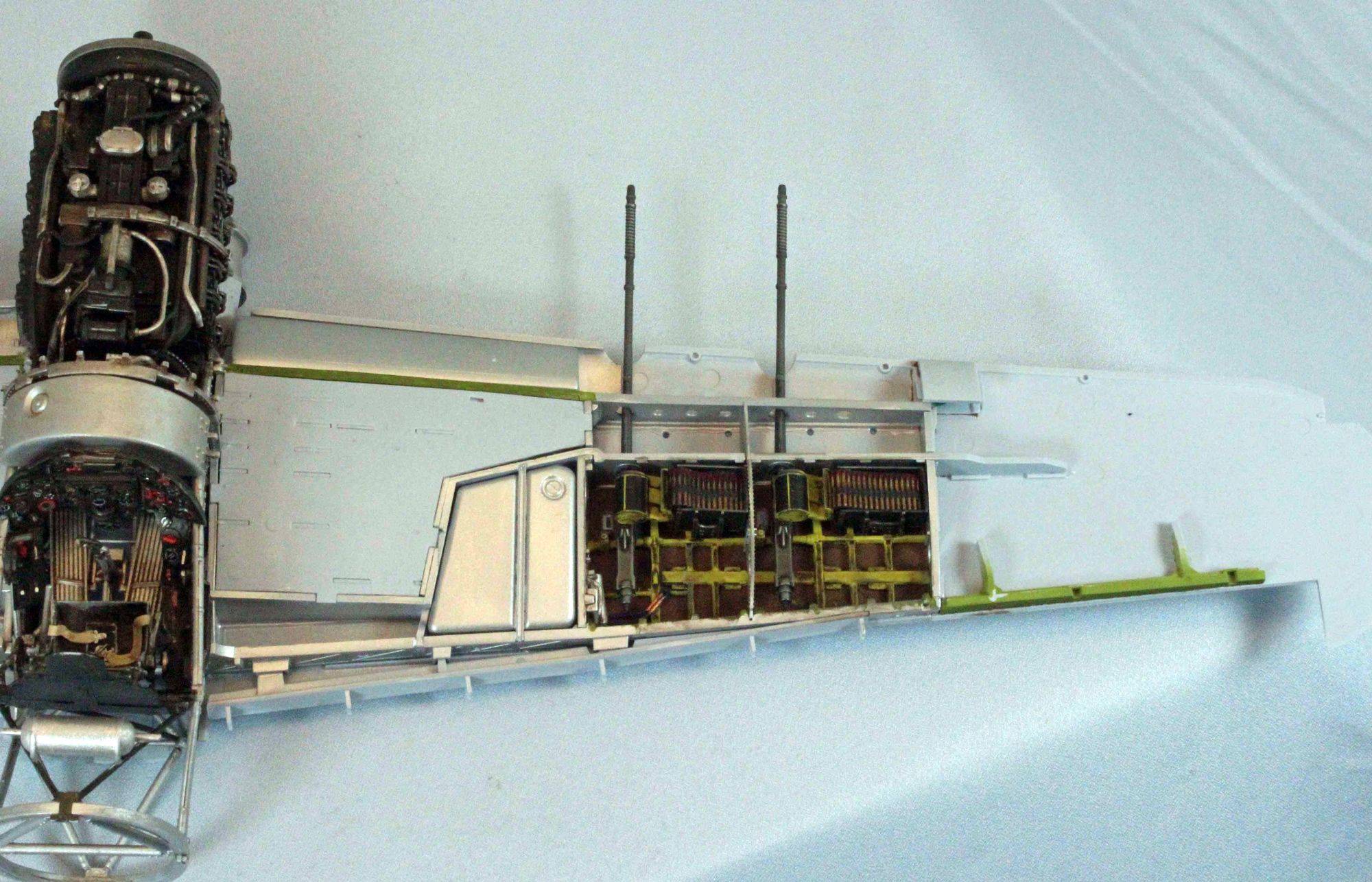
The Hispano Cannon and Wing Bays
While the detail in the cannon bays looks impressive, there really isn’t much to it, and there is plenty of room for folks who want to spice that area up even more.
I pre-painted the ammunition feed motor (Parts F09/F12) Tamiya XF-4 Yellow Green over a pre-shade of Tamiya XF-69 NATO Black. Once assembled, it must be finished by hand and will require a deft touch and smooth flowing paint (I used Vallejo Model Color 70950 Black). The good news is that Airfix gives you a pretty good edge around the areas to be painted; the bad news is, each half of the motor has a sprue attachment point molded right smack dab on that same edge. Ouch.
I painted the electric cables Tamiya X-4 Blue and Testors (Enamel) Copper. I pre-shaded the ammunition can in Steps 119-120 using Alclad Black Primer & Microfiller, followed by a light coat of Alclad Duraluminum. The Hispano cannon were each given a pre-shade coat of Tamiya XF-69 NATO Black, followed by a light spray of Alclad Duraluminum because I wanted them to have a slightly different look than the ammunition cans. Note: You will not see the damper rods (Parts F35), nor the entire front 2/3rds of the cannon barrels for that matter, save the very front tip of each gun.
Needless to say, the fit of these parts was so good that glue was not even needed, including the cannon. Airfix chose to provide solid gun barrels in the kit which, in this scale, requires you to drill out the ends. Never my strong suit, I knew that any mistake made would be hard to cover up. My plan was to assemble the guns, takes some pictures, snip off the barrels, and then replace the tiny portions that stick out past the barrel sleeves with brass tubing. Having nothing to lose, I decided to try my luck on one of the barrels anyway. 90 seconds and three drill sizes later I had a perfectly hollowed-out barrel-end. Repeating the process, I had all four done and cleaned up in less than ten minutes. I attribute my success more to the soft plastic Airfix chose to use in the kit, however, than to my own skill at carving centered holes in plastic.
Parts not used:
All the Parts in Step 107.
All the parts in Steps 113, 114, 119, 120, and 124 (except for the gun barrels).
All the Parts in Steps 125 and 126
Parts G14/G15 in Step 127.
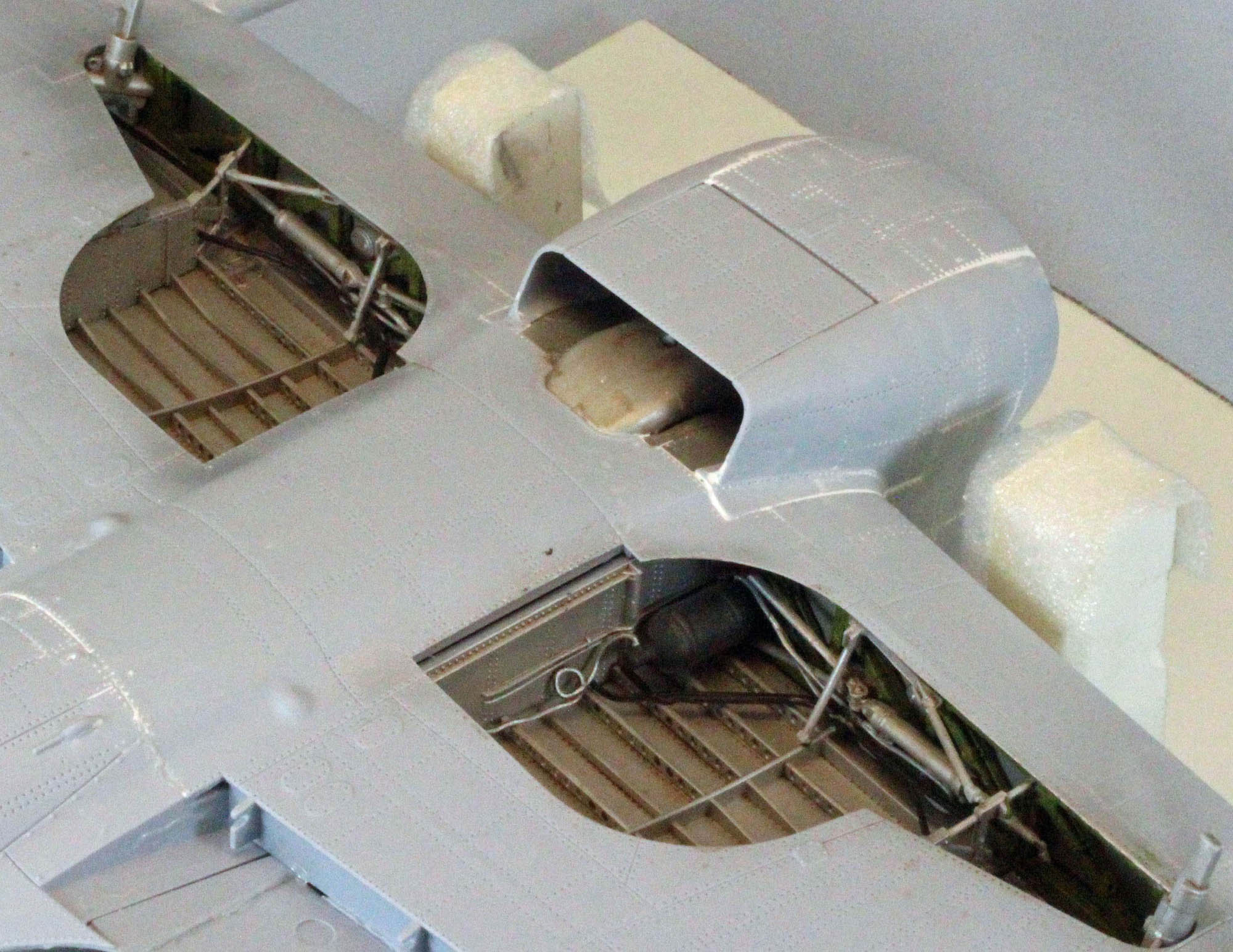
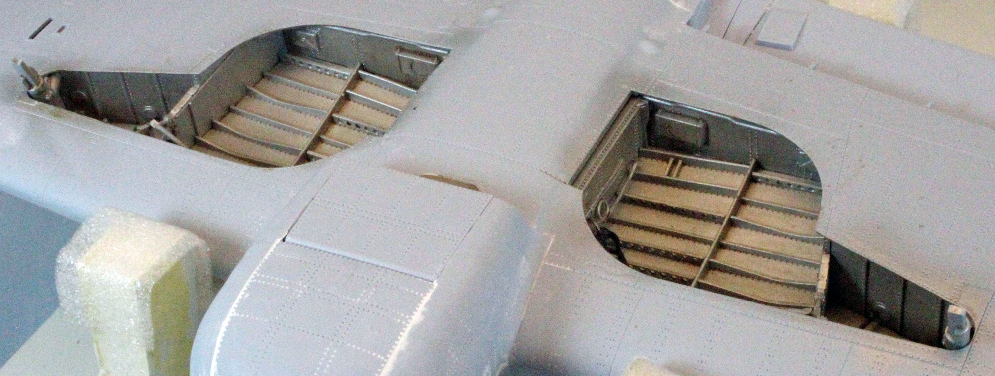
The Wheel Wells – Part 1
Airfix gives you the option to model the landing gear deployed or stowed, and they sell a nice after-market stand if you choose the latter (I finished my Typhoon with the gear down).
The inner ‘roofs’ of the exposed wheel wells are single pieces of plastic that are quite a production. Each piece bends slightly along several axis and is augmented by seven reinforcement joists. Each joist is slightly different from its neighbor, so again, caution must be used to keep them straight after separating them from the sprue.
To this are added a variety of cables, boxes, etc., and while there is a lot of clean up to be done on each part, the fit of everything is perfect.
Before dropping the ‘floors’ onto the top of the lower wing, I painted the beacon lights (Parts R07/R08) Tamiya X-27 Clear Red.
For some reason, Airfix has you pause with the wheel wells here (Step 131), and doesn’t pick them up again until Step 175, although everything needed is in place to finish them. I assume this is because the added bulk of the fuselage and wings might be considered easier to work with than what you have at this point in the build. I built a jig out of foam core, however, to hold things in place (even upside down), so if I were to do it all over again I would skip ahead now and finish the wheel wells in one shot, and then come back to Step 132 before continuing.
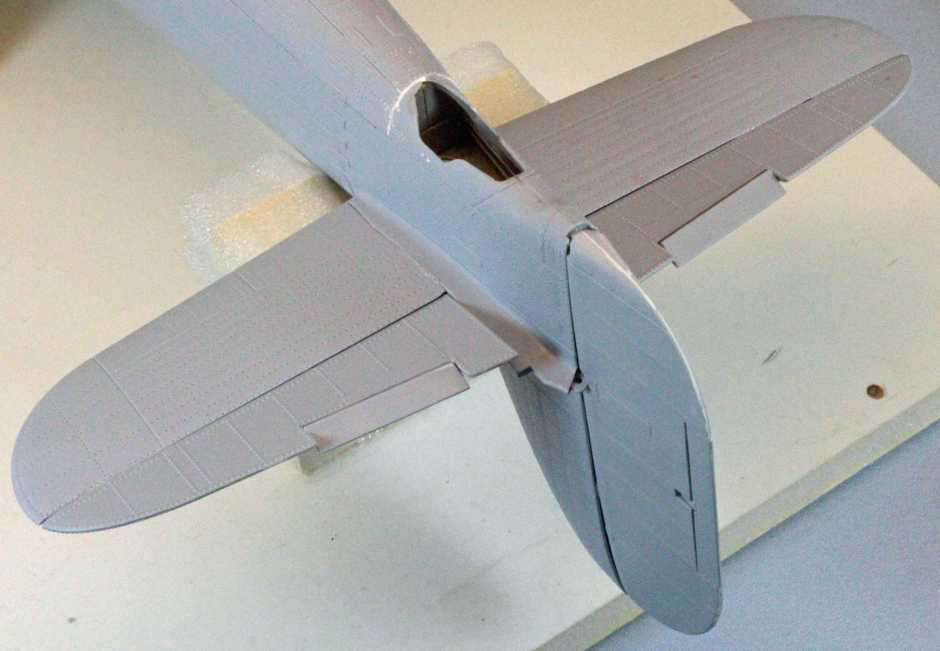
Finishing the Wing
Steps 132–142 finish the huge Typhoon wing, and I have to tell you, the result is something to behold. This model is HUGE. The two outer portions of the lower wing slip right on giving you the first impression of just how big the plane will be. Based on the scheme you are building, you can decide to include the clear, wing-mounted landing light sections or model them covered up, as in my version. Once those are dry, the two upper wing sections drop right down on to the lower wing. Once again, I used a variety of clamps to hold the wing together while the glue dried, but they weren’t really needed – the fit, even over all the structure underneath, is that good. I left the clear wingtip lights off for later, and modeled the service step on the starboard wing root closed. Leaving it open would add busy complexity to the wing-walk decals coming later.
Use caution when snipping the Hispano barrel sleeves off the sprue – both bottoms and tops are ‘sided’ so you need to keep the eight parts separate as you assemble them. In the end, they will only fit one way (thank you, Airfix) but you can save yourself the anxiety I experienced when (at first) nothing seemed to line up right!
The engineering and design here is fascinating. Airfix took a rather complex problem and designed each of the eight pieces to fit together perfectly using different thicknesses of plastic and a set of bent prongs that grab and hold a part that protrudes from the inner wing to keep everything in place. I am impressed.
The Tail
Airfix provides both types of tail in the kit, the smaller tail that I used is earmarked for the first, third and fourth schemes, and the larger ‘Tempest’ tail for the second scheme. The tail is split into two halves and I added each tail half to each fuselage half as instructed. The last step you take before attaching the two fuselage halves is to add the rear tail wheel well and strut hardware. I painted the wheel well and the exposed fuselage areas Tamiya XF-16 Flat Aluminum.
Bringing the Fuselage Together
If you are building the model using any of the three display options offered by Airfix, the instructions tell you which parts to remove from each fuselage side before gluing them. I made those cuts long ago for the (fourth) display option that I decided to use (see Part 1 of this review for more information).
Airfix has designed the fuselage to come together in three parts; right and left fuselage sides, and a lower center section that runs from the wing roots back to the tail. The instructions will have you glue each fuselage side to the superstructure, one at a time, hoping things will align once the two sides are on. My experience with this type of approach is that if there is a problem, I end up with a visible seam line along the top of the fuselage where the halves meet. Personally, I’d rather have all of my ‘big’ problems safely out of sight – in this case, along the bottom of the aircraft somewhere, and looking around the internet and my references, it seems that I am not alone in this respect. Consequently, I decided to glue the fuselage halves together and then once dry, attach that to the superstructure as one piece.
This approach worked out well. Once the two halves were glued together and allowed to dry overnight, all I had to do was slip the fuselage over all the bumps in the front end and between the wing roots. The fit along the wing root on each side is not perfect, but I’m not sure it would have been any better had I followed the instructions (in fact it probably would have led to that center-line gap I was concerned with). An application of water-based Deluxe Materials Perfect Plastic Putty here and there fixed everything up without sanding.
Some folks had some fit issues with the underside center section, but mine snapped into place perfectly once the rest of the fuselage was together.
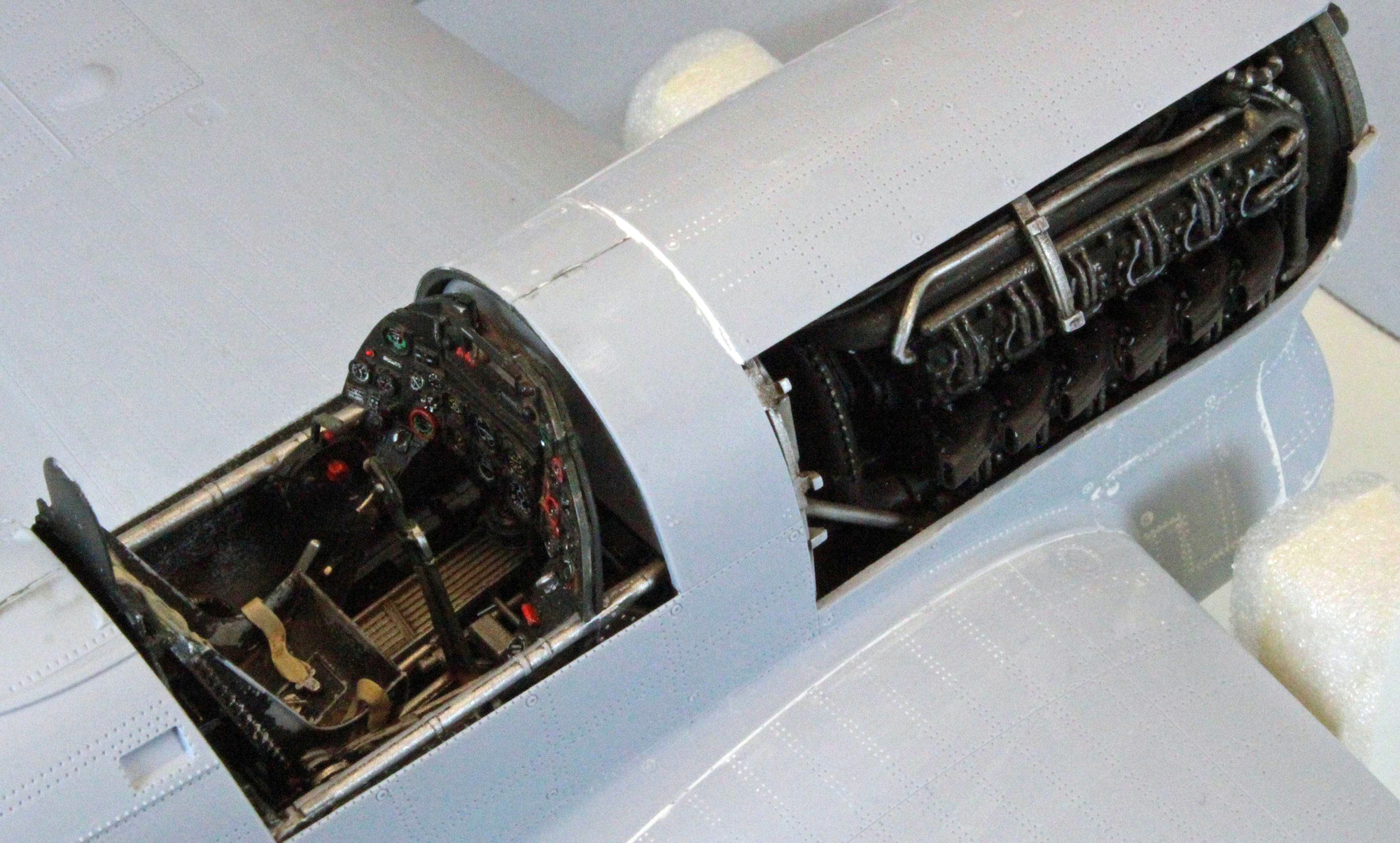
The exhaust manifold pipes on each side of the engine are attached in Steps 151-152. Each pipe has a weld line down the middle which I didn’t recognize as such before I sanded one of them off while preparing the parts for painting. A quick application of one of Archer’s excellent surface detail product replaced the missing seam. I mounted the pipes on a chunk of clay and painted them Alclad ALC123 Exhaust Manifold over a primer coat of Alclad ALC309 Black Primer and Microfiller, before gluing them on each side of the engine, starting from the rear and working forward.
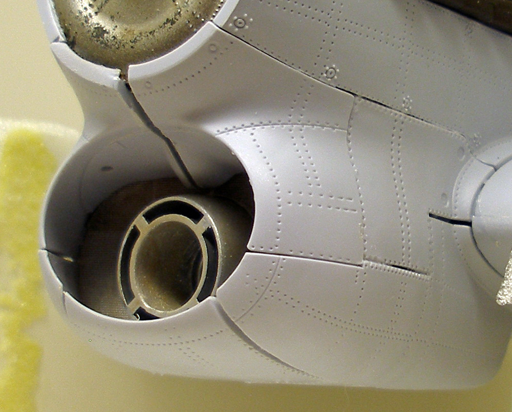
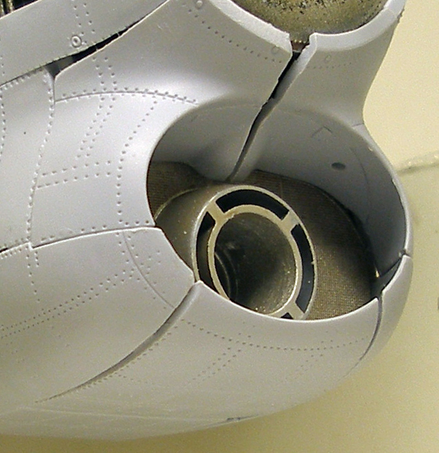
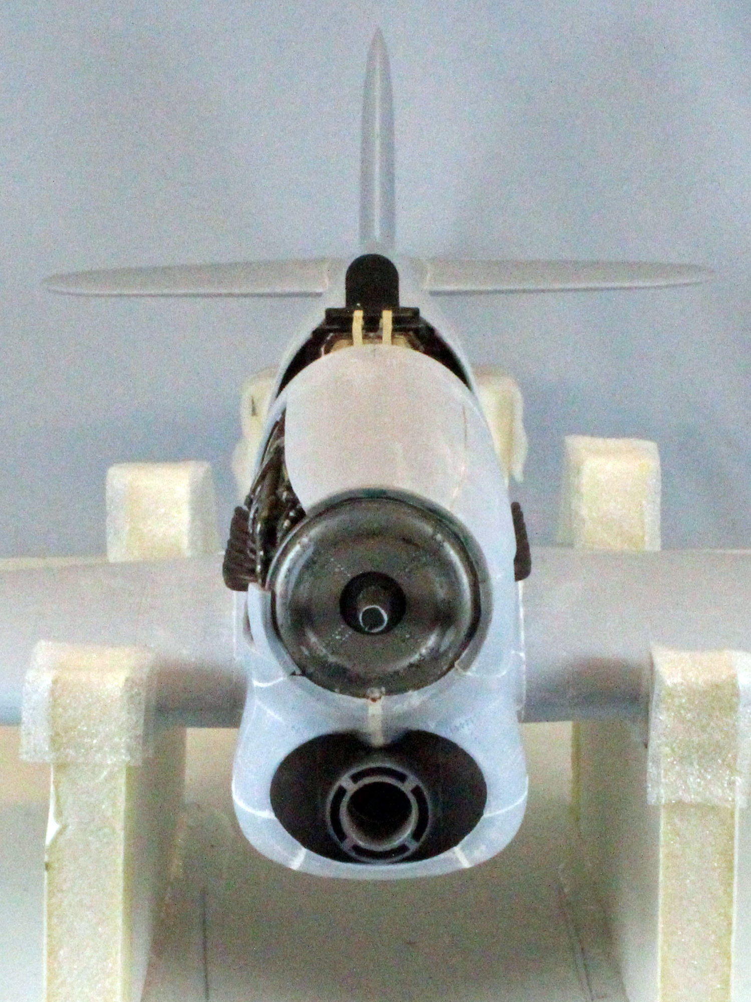
The Front End
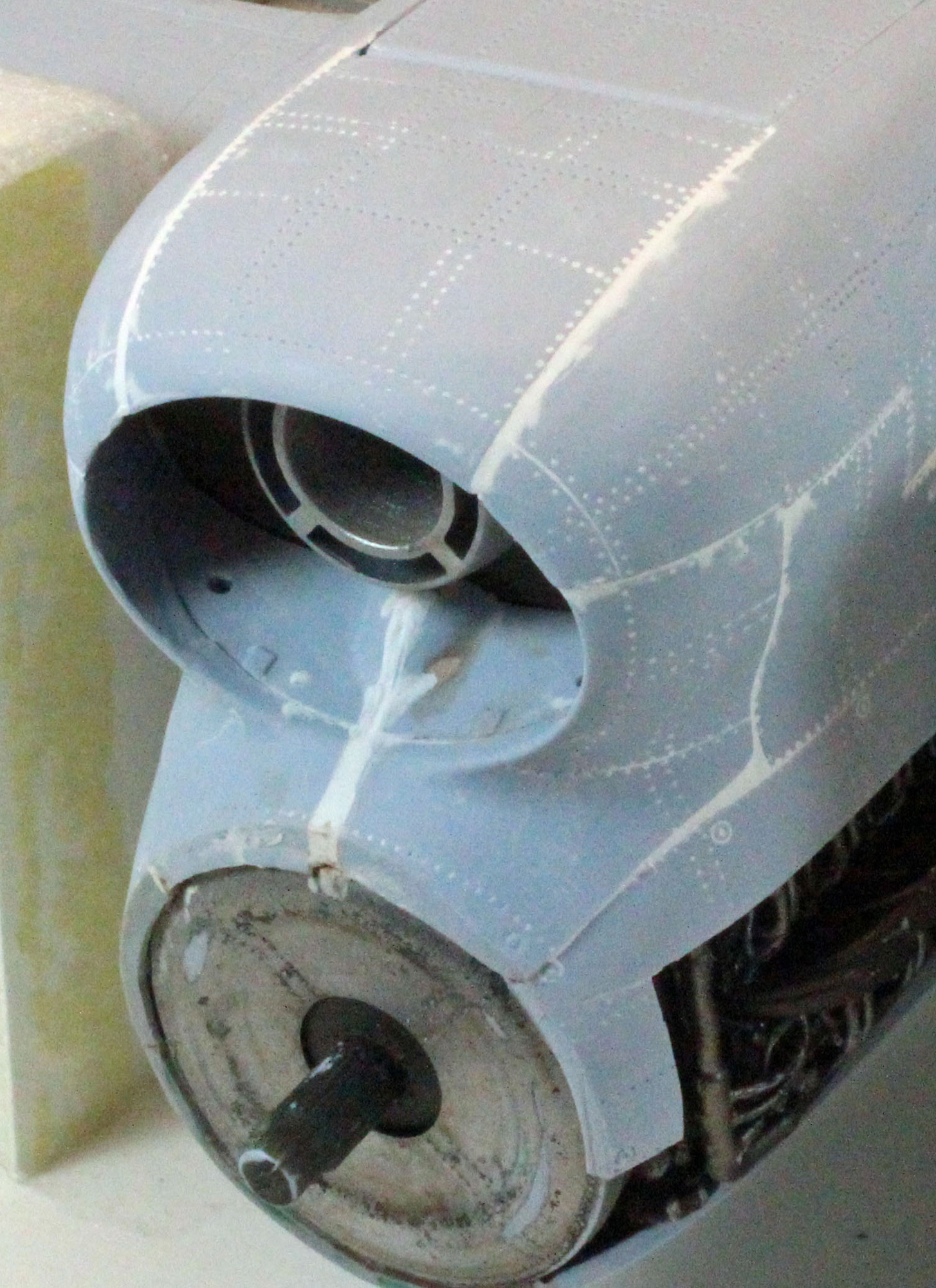
Airfix tried their very best to stay true to the actual panel lines around the front of the aircraft, yet still make the model buildable. As a consequence, there are no fewer than eight significant parts that need to converge perfectly around the spinner base in front of the engine. Unfortunately, the fit comes up short, and required some filling and fiddling – in my case, a whole lot of filling and fiddling. What makes matters interesting is that the area is question is essentially un-sandable due to the compound curves on every surface, and the amazing raised and recessed detail throughout. Consequently, it comes down to preserving the round opening in the front by carefully lining up the edges and then filling the resulting gaps with Perfect Plastic Putty. I had to saw Part N09 in half (!!) to preserve the upper curve, which resulted in a gap almost 1/8th inch wide (see images). Yuck.
I started by test fitting the parts that surround the spinner base, using Tamiya tape to hold things together. This exposed significant gaps along several lines, although the gaps are uniform and were mostly simple to fill (see photos).
Once I knew where the problems were, I took everything off and started with Step 153 and proceeded in the order Airfix instructs.
You can model the rear of the air intake open or closed, as well as one of three air-scoop configurations, based on the scheme you are building.
I looked around the internet and in my own reference materials and failed to find even one description of the assembly process up front. Either the builders left the entire front end uncovered or they built it up and didn’t talk about it to any useful extent, citing ‘some cleanup required’. Airfix, to their credit, tells you in the instructions to pay particular attention to Steps 77-81 (the steps where the oil-cooler/air intake come together) – but I did, and I remember having a fit problem (which I discussed in Part 1 of this review), so perhaps the front end problems I had were a result of that. I don’t know. Nevertheless, the area cleaned up OK, but unfortunately, I’m afraid the fix will prevent this build from being competitive.
The upside is that once I began to attach the nose parts, a metamorphosis started to take place – the unmistakable lines of a Typhoon emerged – big, bad and beautiful!
Flaps, Ailerons and Tail Planes
The Typhoon has quite a few control surfaces, and Airfix gives the builder a variety of options to pick from. All control surfaces can be built in open/closed, left/right configurations, some of which are determined by the scheme you are building. The fit is back to perfect again (!). The only fiddly part was in Step 171 - interesting design here. It isn’t clear from the instructions how Part I06 slips in, but if you give it a little pressure, it will pop into place.
Steps 166 through 172 manage the horizontal and vertical tail planes, while Steps 199 through 202 (waaay later) bring the wing flaps and ailerons together. I can’t figure out why Airfix decided to break the assembly of these similar items into two parts; I did them all at once and only continued on to the wheels wells once the entire superstructure and control surfaces were together and the glue had set.
While the control surfaces are movable, I suggest that you check your references for the proper placement and glue everything to hold fast. At rest, the two outer flaps should be placed in accordance with the position of the control stick in the cockpit, and opposite from one another (one up and one down, or both in neutral (flat) position). I didn’t like the look of having one of the flaps up, so I glued them both flat. The way the flaps are assembled, however, (around a long bar with three attachment points (see Steps 199-200)), they want to both point downward, and I had to use clamps to position and hold them in the neutral position while the glue dried.
I attached the cover to the port-side cannon bay, and left the articulated covers for the open starboard bay off until later.
Wheel Wells – Part 2
If you wait until Step 175 to finish the landing gear bays instead of doing so back in Step 132, you will need a sturdy jig to hold the aircraft upside down, and the jig will have to be movable along several axes. This is because the fit of the parts is a little tight in places and the size of the overall superstructure at this point is a bit cumbersome to flip around.
Before painting I assembled the main wheel struts (Steps 183/184), and wheels (Steps 188/189), and the main doors (Steps 190/191).
The wheels come in two halves, leaving a noticeable seam down the middle of each. The only technique I know that is up to the task of removing a seam line while not affecting the curvature of this kind of part is using Super Thin CA glue and sanding pads. I first brush a thin layer of glue along each seam, hit them with accelerator, and then employ a padded sanding set used by my car modeling friends produced by Micro Mesh. The six pads are used in sequence, from 1500-4000 grit, and leave a baby-smooth finish when done.
I painted all the parts in Steps 175 through 197 before assembly:
- Forward hydraulic lines (Parts D34/35) Alclad Black Primer & Microfiller.
- Insides of the wheel well doors (Parts D30/31, C58/59), Hydraulic actuators and lines (Parts D50, D51), brackets (Parts D53/56), and the lines coming out of the two large cylinders (Parts D54/55) Tamiya XF-16 Flat Aluminum. I painted the rest of the two cylinders Tamiya XF-69 NATO Black. I wanted to distinguish the black parts further so I went over the cylinders with Uschi Steel pigment using a rubber artist’s blender to bring out a little bling.
- While I had the paints out I pre-shaded the main strut assemblies in Steps 183 and 184, the tail wheel strut parts, and the wheels with Alclad Black Primer & Microfiller, finishing them with Alclad Duralumin (struts and wheels) and Model Master 2024 U.S. Army Helo Drab (tires).
Once the paint had dried, I started building up the wheel wells. The majority of the parts are crammed up into the front of each well and overlap each other. I could not get the initial two parts (D34/35) to fit well – there is a little bump near where the lines split that rides up and over one of the joists in the well and these just wouldn’t line up for me. Since everything else is placed over these parts, the whole assembly on my finished model ended up being a little ‘customized’. No worry (for me) – since it still looks pretty good. Once everything was dry I gave the wells a good filter of Mig Wash Brown and a pin wash using Mig Dark Brown.
I left off the main strut assemblies, the wheels and the gear doors until the end of the build so they wouldn’t get in the way during painting and finishing.
Conclusion
I am well into this project now and one thing I have learned is that this kit is not forgiving if you get something wrong. As I said in the first part of the review, Airfix has put a lot of effort into making sure the parts fit, and if they don’t, there is a good chance that you’ve got something wrong. I only had a few fit problems, and I admit these could have been self inflicted. That said, I really thought I paid attention to the instructions and I dry fitted everything, several times, before committing glue. If this wasn’t a review, I fear that I might have committed the kit to my ‘closet of unfinished projects’ when I encountered the ‘nose problem’ in Step 156. But this is why I love doing reviews – the time commitment forces me to stop over-thinking things, and to just ‘do it’ and move on. Each challenge is a learning experience that improves my skillset, and that’s a good takeaway no matter how you look at it.
While the nose area of my Typhoon may not come out perfect in the end, the aircraft still inspires awe at this point, even unpainted. The sheer size of the model, and the masculine lines and intimidating look of the Typhoon trumps any downside I’ve encountered. This will be one great looking aircraft in my model case, and Airfix has done a superb job getting me there. As I said in Part 1 of this review, this has been a thoroughly enjoyable modeling experience.
I recommend this kit to all modelers who are up to the small challenges that a kit with so many parts and options will offer. I suggest that you make your big decisions up front, spend the time to carefully clean the parts thoroughly once separated from the sprues, and dry-fit everything. Slow down, use your references, and enjoy the ride!
First segment: Internal fuselage and wing structure, cockpit, engine and front end.
Second segment (this one): Wing, gun bays, wheel wells, fuselage and tail.
Last Segment: Weapon stores, final assembly and finish.
I would like to thank Hornby Airfix for providing this kit for review, and to IPMS USA for giving me the opportunity to review it.